Attention: Remember that the dust generated during the wear of the friction linings of the clutch disc may contain asbestos, which is harmful to health. Do not blow off dust with compressed air and try not to inhale it. Do not use petroleum-based solvents to clean clutch components, use only special brake cleaners or pure methanol. Store used rags in a sealed container.
1. The slave cylinder assembly with release bearing is attached to the inside of the clutch dome and requires the gearbox to be removed to remove it (see Part B). Wipe the outside of the cylinder thoroughly.
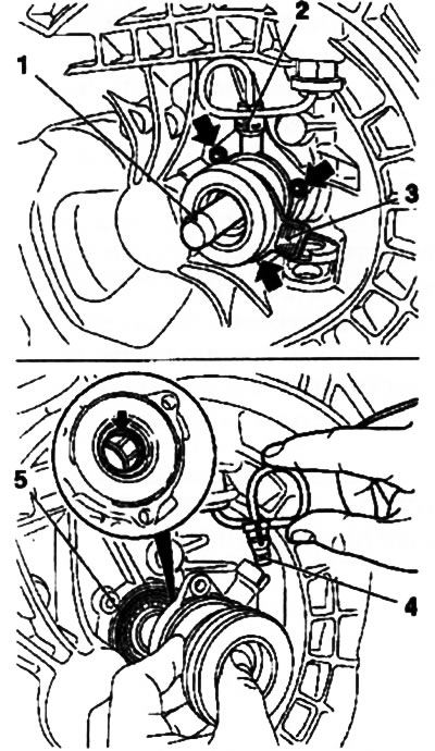
2. On manual transmission F13/F17 (all modifications) to prevent failure of the release bearing during removal, install a special holder (Red) (see resist. illustration). Install the KM-6157 special tool in the bearing hole, remove the retainer of the hydraulic line connecting fitting and unscrew the 3 fixing bolts.

3.2. Removing the release bearing (Manual transmission F13/F17) - the arrows indicate the fastening bolts: 1. Fixture KM-6157; 2. Retainer of the connecting fitting; 3. Special holder (Red); 4. O-ring fitting; 5. O-ring
3. Remove the slave cylinder assembly with the special tool while pulling out the connecting fitting of the hydraulic supply line (see illustration 3.2) from assembly.
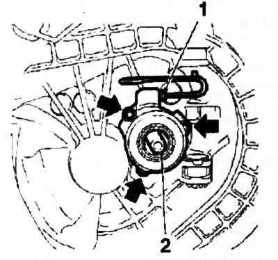
4. On the F23 manual transmission, install the special tool KM-6059, then loosen the nipple connector nut and disconnect the hydraulic line from the cylinder (see resist. illustration). Turn out 3 fixing bolts and remove assembly of the cylinder.

3.4. Removing the clutch slave cylinder using the KM-6059 tool (2) (Manual transmission F23) - the arrows indicate the fixing bolts: 1. Nut of the hydraulic line union connection
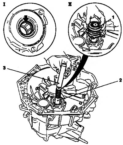
5. On models with the Easytronic system, the mounting of the slave cylinder assembly is almost completely identical to the mounting on the F23 manual transmission. To remove / install the assembly, the KM-6157 tool is used (see resist. illustration).

3.5. Assembly installation (1) slave cylinder on models with Easytronic - the arrow indicates the release bearing seal: 2. Inlet (primary) gearbox shaft; 3. Adaptation KM-6157
6. After disconnecting the hydraulic line, clean up any spilled brake fluid.
7. Remove the sealing ring installed between the cylinder and the gearbox housing - the ring must be replaced without fail. Take precautions to prevent dirt from getting into the box.
8. Check the condition of the release bearing seals (indicated by an arrow on the callout) and sealing ring of the connecting fitting (see illustration 3.2).
9. A failed slave cylinder cannot be repaired. If brake fluid leaks develop, replace the cylinder assembly.
10. Before installation, make sure that the mating surfaces of the cylinder and the gearbox housing are absolutely clean and dry. Fit a new O-ring into the receiving groove on the transmission case. Lubricate the inner O-ring of the cylinder with clean transmission oil and carefully install the cylinder onto the input shaft of the manual transmission using the special tool (KM-6157 or KM-6059 - depending on the model).
11. Further installation is carried out in the reverse order of removal. Don't forget to bleed the hydraulic circuit (see Section 4).

Visitor comments