Explanations for Body Control Point Diagrams
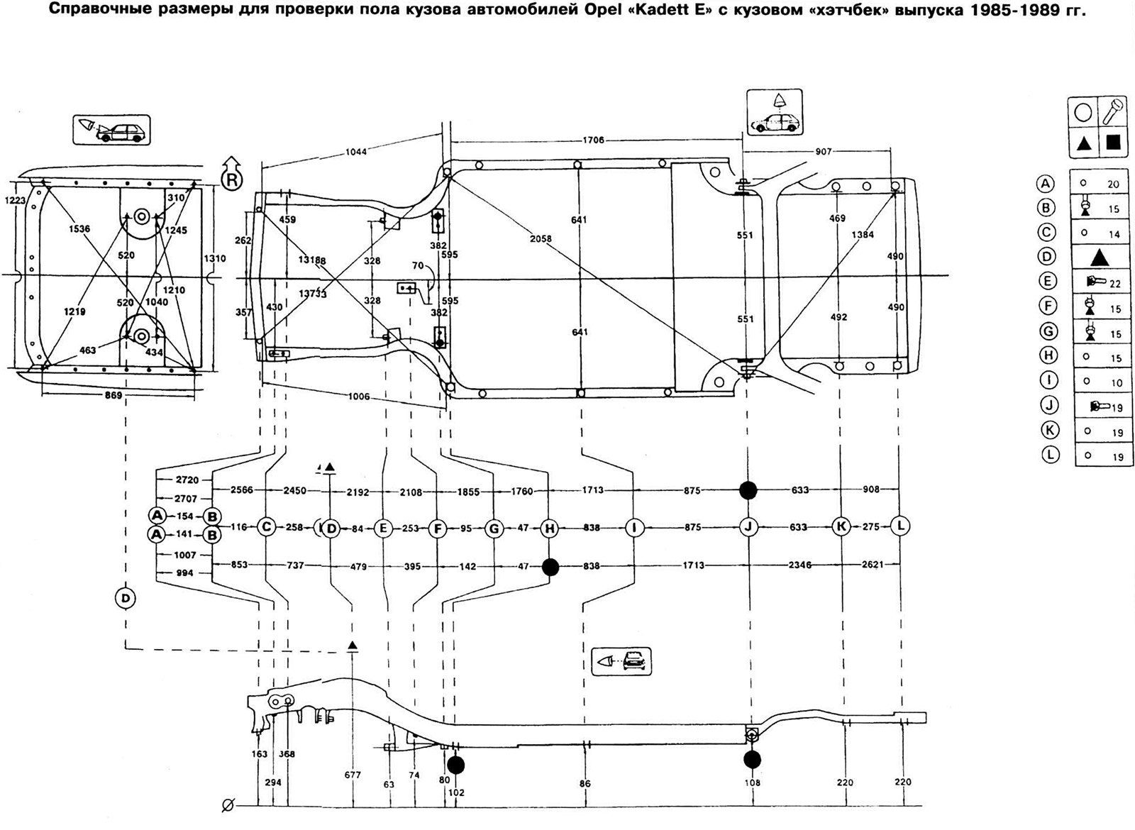
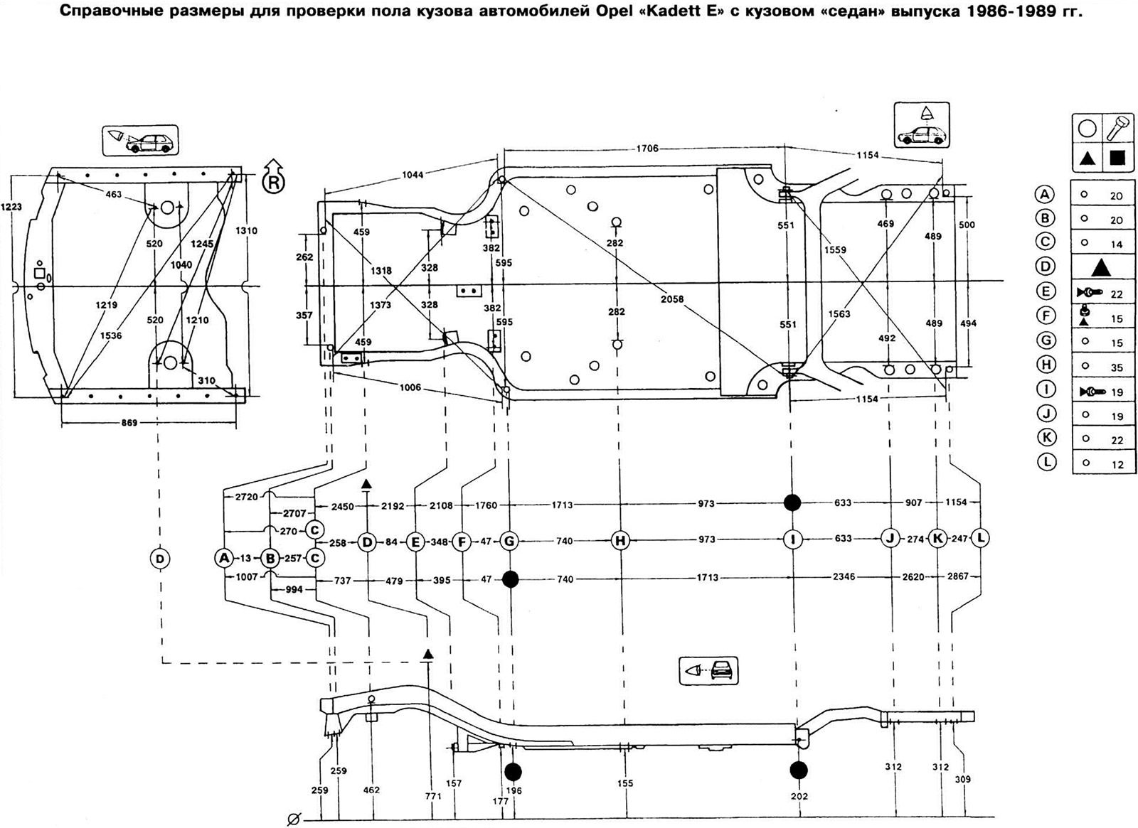
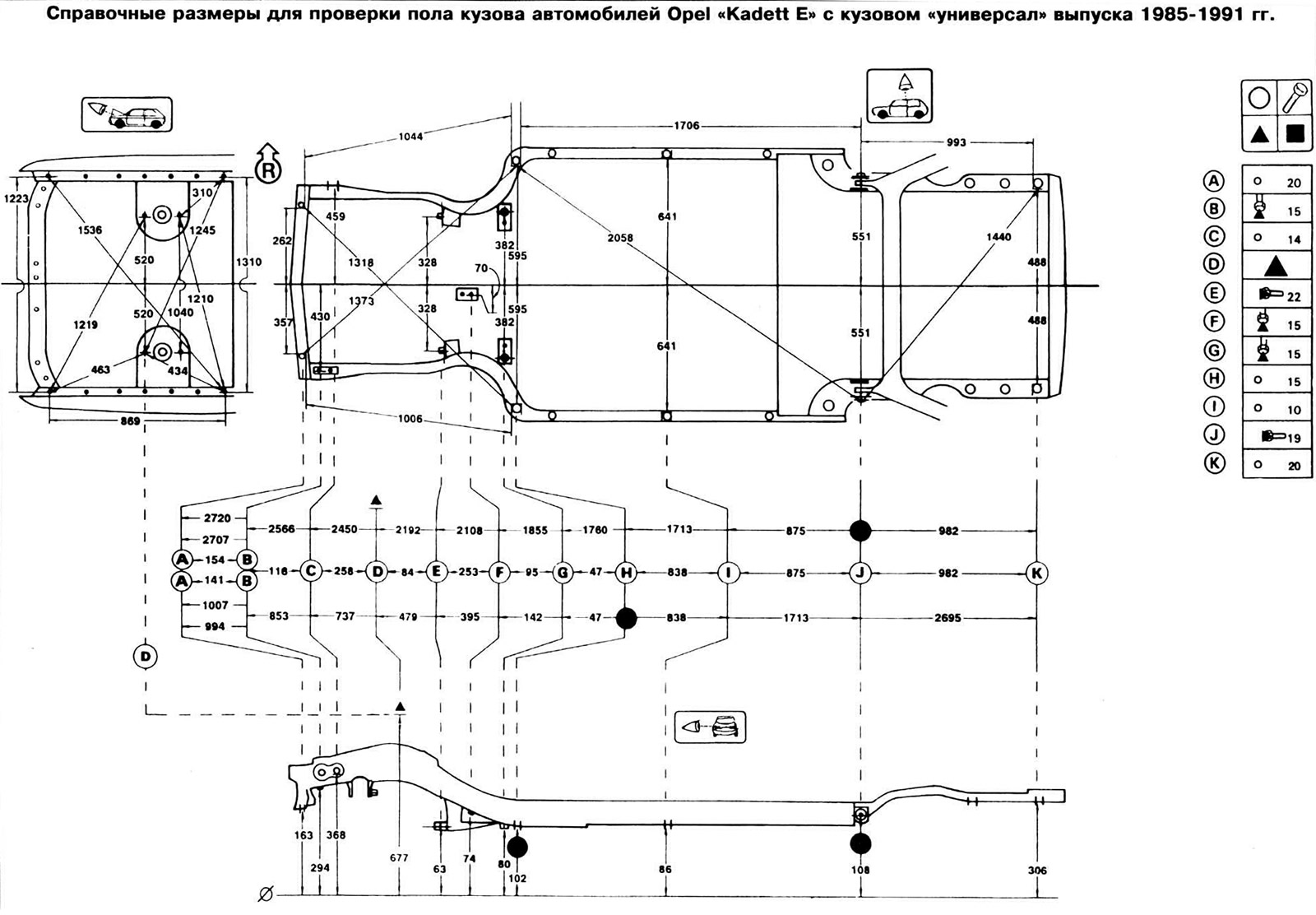
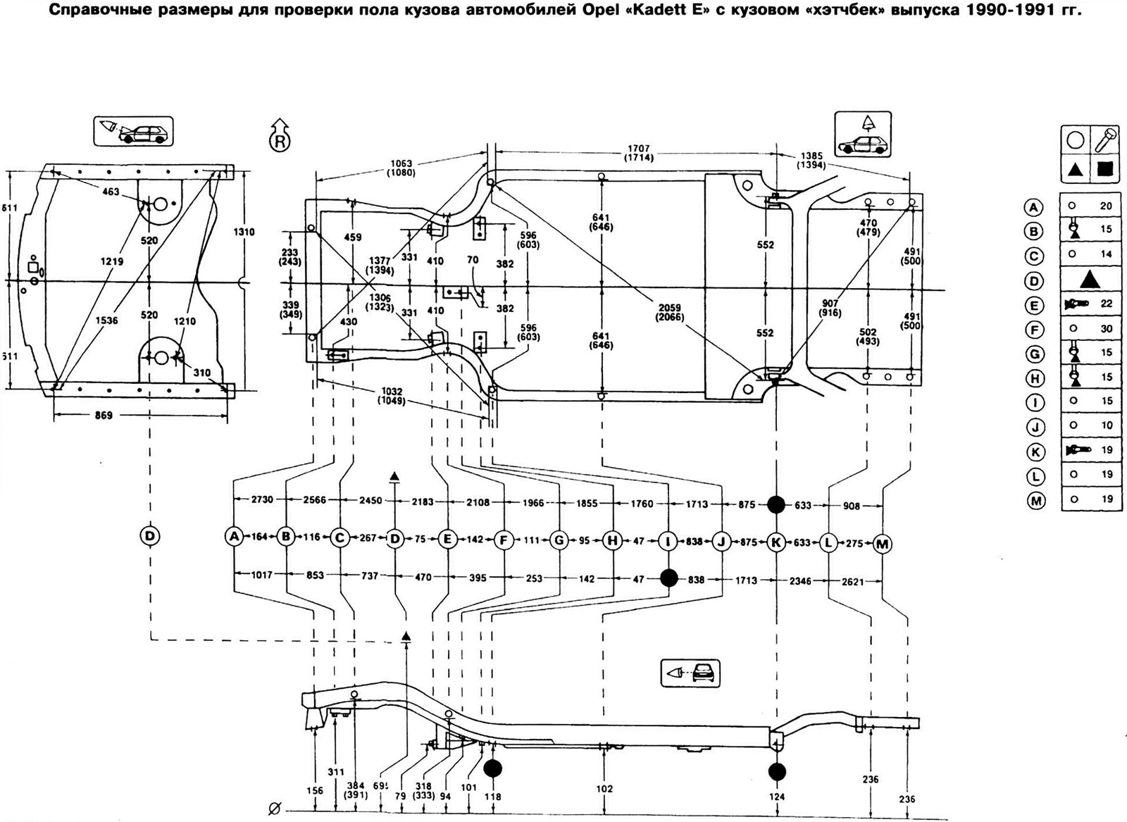
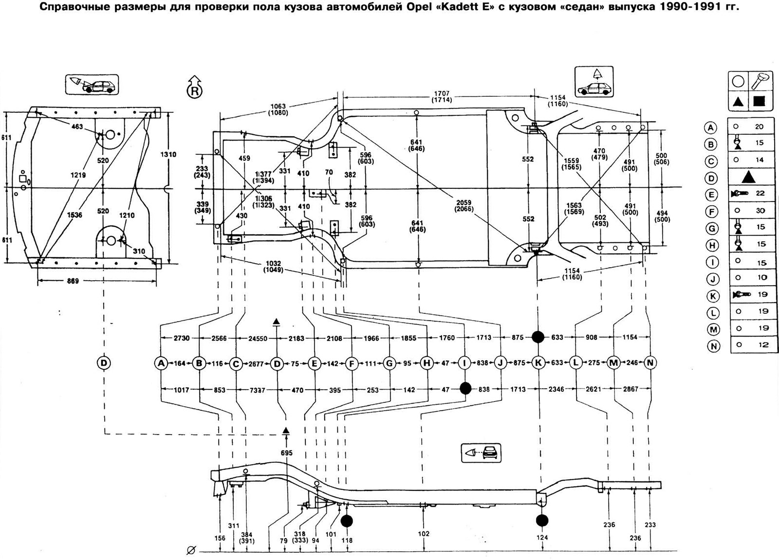
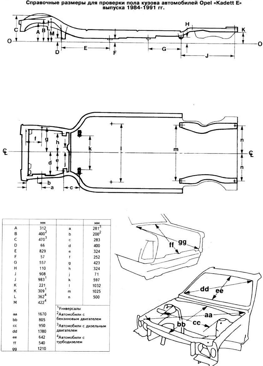
Body checkpoints are labeled A, B, C, etc. Each diagram has a table in which the dimensions of the corresponding holes and bolts are indicated opposite the control point.
In the upper diagram, the dimensions between the control points along the diagonal and the width are calculated to the nearest edge of the hole. Dimensions between bolts, nuts, studs, non-removable plugs and rivets are measured between their centers.
In the top diagram, all dimensions, except for width dimensions, are measured between control points. To check them, it is necessary to use a measuring rod, the ends of which must be extended to the same length. For the same purpose, if body parts do not interfere with the measurement, a metal tape measure can be used.
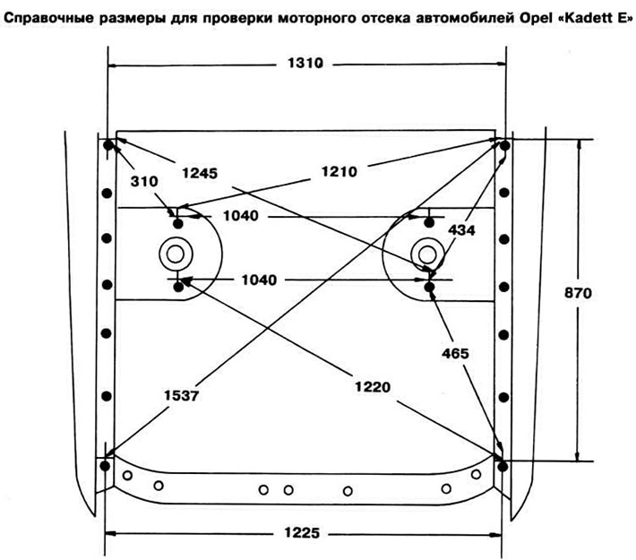
On the diagram of control points of the engine compartment, all dimensions, except for the dimensions between the fastening elements of the suspension elements along the width, are shown between the control points.
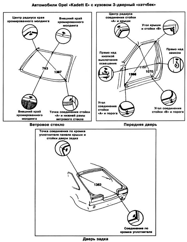
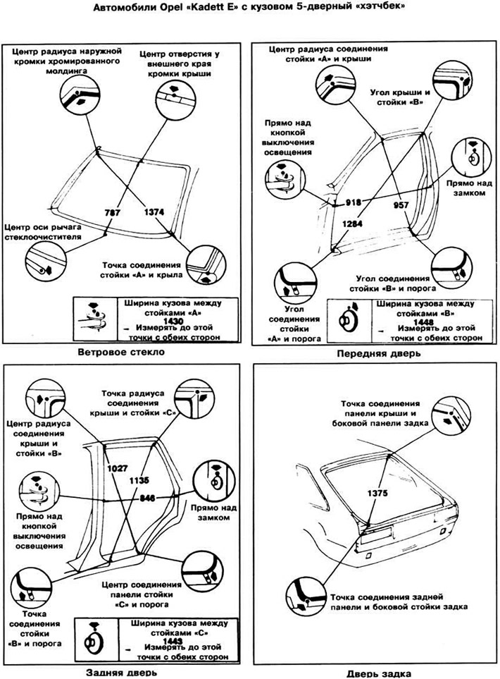
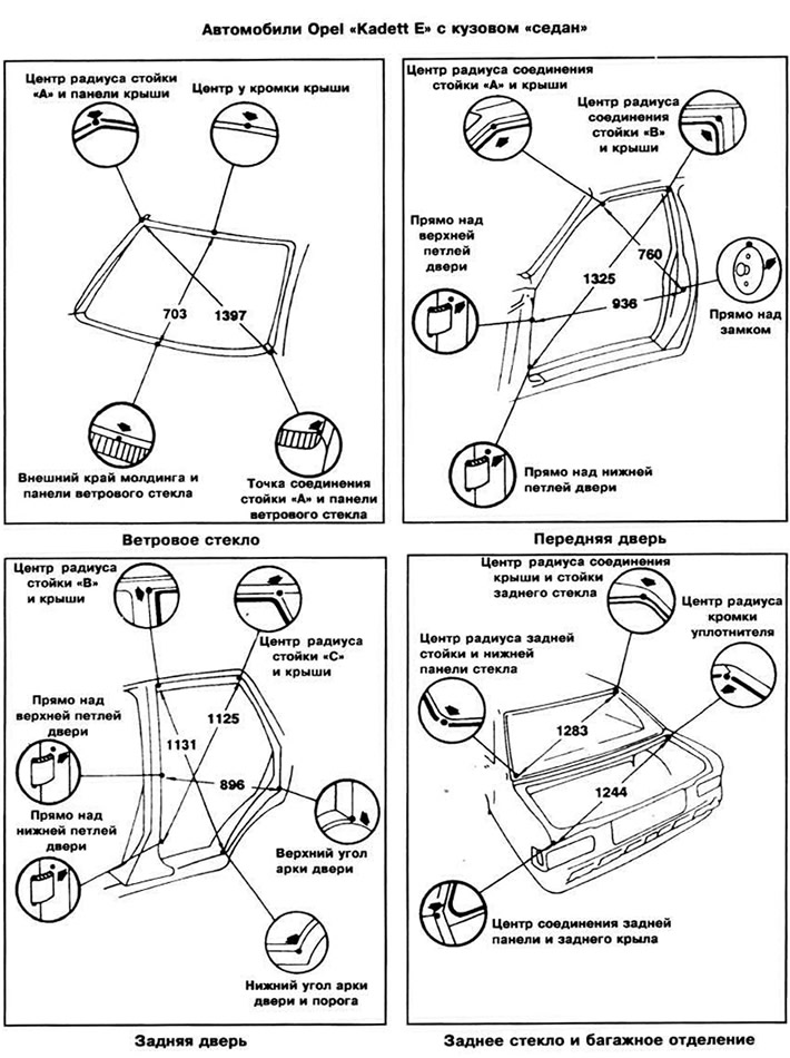
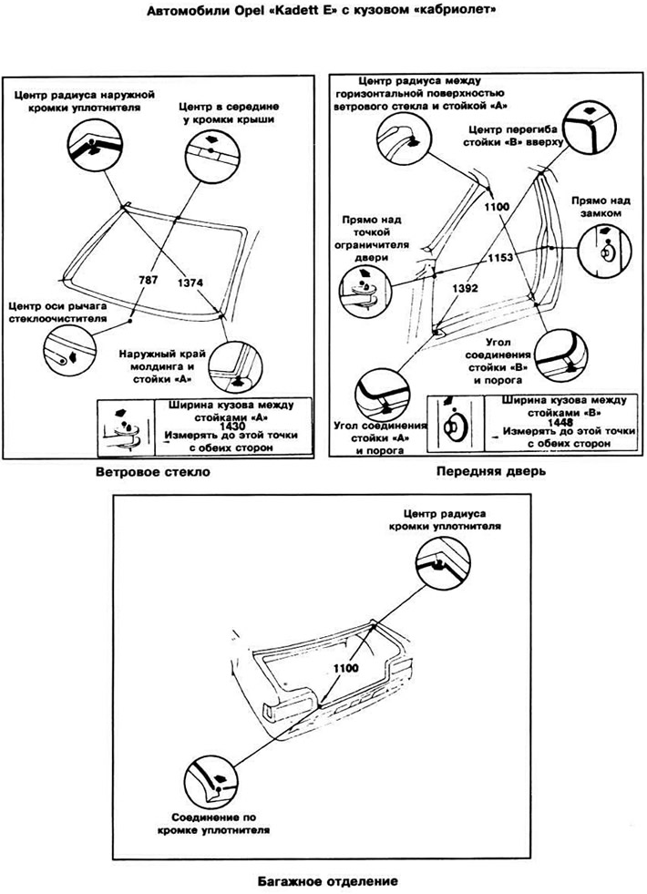
Dimensions are in millimeters and rounded off. The tolerance is +5 mm. The body parts shown on the next page contain callouts for each section that show the exact location of the measurement point, as well as measurement instructions.
Open large image in new tab →
Open large image in new tab →
Open large image in new tab →
Open large image in new tab →
Open large image in new tab →
Open large image in new tab →

Visitor comments