Removing
Attention! The cylinder head should only be removed from a cold engine.
1. Cars with air conditioning.
Disconnect the A/C compressor and mount it to the body without disconnecting the refrigerant hoses/pipes from the compressor.
Attention! All work relating to the removal, installation of the air conditioner, draining and refilling the refrigerant should be entrusted to a specialized workshop.
2. Remove the windshield wiper motor (see relevant chapter).
3. Unscrew the mounting bolts and remove the cylinder head cover (see relevant chapter).
4. Remove the camshafts (see relevant chapter).
5. Remove the hydraulic valve lifters.
6. Remove the clamp 2 fastening the radiator 3 cooling the exhaust gas recirculation system (see illustration).
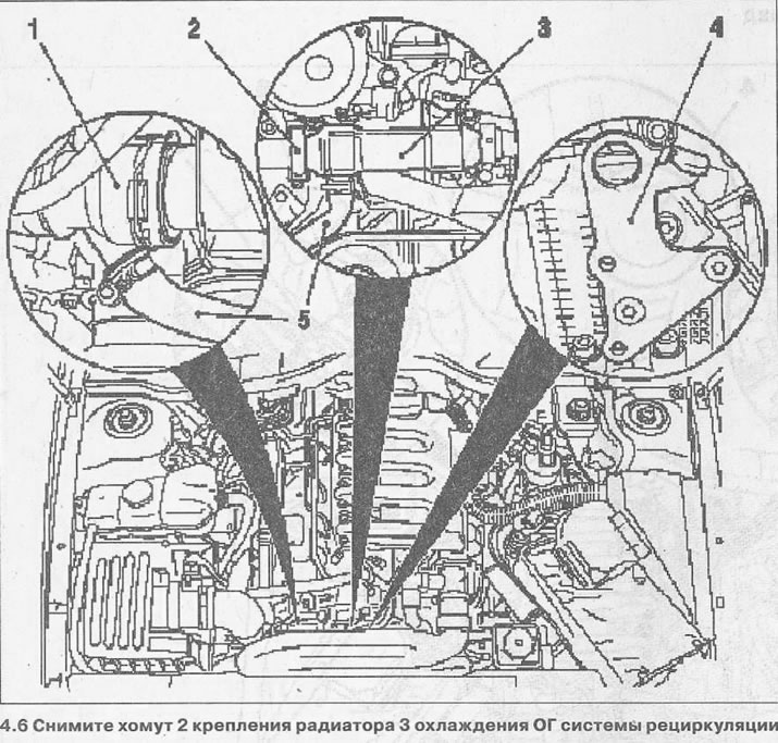
7. Disconnect the hose 5 of the cooling system from the branch pipe 1 of the exhaust gas cooling radiator of the recirculation system (see illustration 4.6).
8. Unscrew bolts of fastening and remove a radiator of cooling OG of system recirculation together with the details fixed on it.
9. Unscrew the mounting bolts and remove the lugs 4 from the cylinder head to lift the engine (see illustration 4.6).
10. Unscrew the nut 6 on the injection pump using the KM-812 key (see illustration).
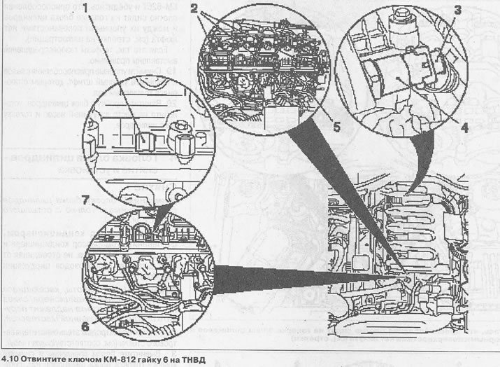
11. Unscrew the union nut 7 from the pressure chamber 5 using the KM-812 wrench (see illustration 4.10).
12. Close the opening on the pressure chamber using the plug 1 KM-6273 (see illustration 4.10).
13. Disconnect plug 3 from pressure sensor 4 in the pressure chamber (see illustration 4.10).
14. Unscrew bolts 2 and remove pressure chamber (see illustration 4.10).
15. Disconnect hoses 1 and 3 of the cooling system from the connecting flange on the cylinder head (see illustration).
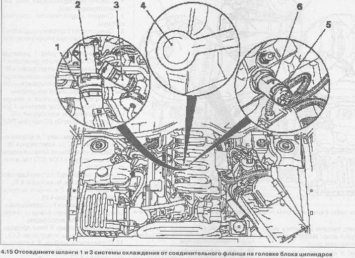
16. Disconnect plug 4 of the preheater (see illustration 4.15).
17. Disconnect plug 5 of coolant temperature sensor 6 (see illustration 4.15).
18. Unscrew the bolts 5 fastening the bracket 6 of the turbocharger (see illustration).
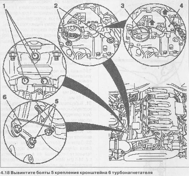
19. Unscrew bolts 1 (see illustration 4.18).
20. Unscrew the bolts 2 fastening the tensioner 3 and the damper 4 of the chain and remove them.
In this case, the tensioner must be shifted down, and the damper must be submitted in the direction of the arrows (see illustration 4.18).
21. Unscrew bolts of fastening of a casing of the gas-distributing mechanism and a head of the block of cylinders (see arrows in illustration).
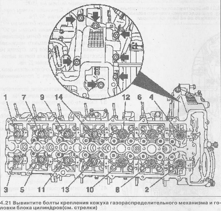
22. Unscrew bolts of fastening of a head of the block of cylinders, acting in sequence of designation of bolts 1-14. Preliminarily loosen the bolts by ½ turn, following the sequence shown (see illustration 4.21).
23. Remove the cylinder head.
Attention! Place the removed head on wooden blocks to prevent damage to the valves.
24. Remove hinged components from the head; it was dismantled for the purpose of inspection and reassembly.
Installation
25. Clean the sealing surfaces of the cylinder head and block and remove seal residues.
26. Check up a head of the block of cylinders on deformation and a curvature by means of a metal ruler, and also measure height of a head.
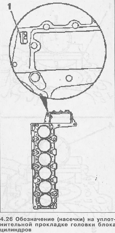
Attention! If, after removing the head, no work was carried out on the cylinder block, as a result of which the protrusion of the pistons could change, then when installing the head, it is possible to lay a sealing gasket of the same thickness as the previous one, with the same number of notches (see 1 in illustration 4.26). Otherwise, the protrusion of the pistons should be measured and a gasket of the required thickness selected.
27. Measure the protrusion of the pistons of the cylinders in order to select the sealing gasket of the required thickness.
Attention! The protrusion of each piston should be measured separately.
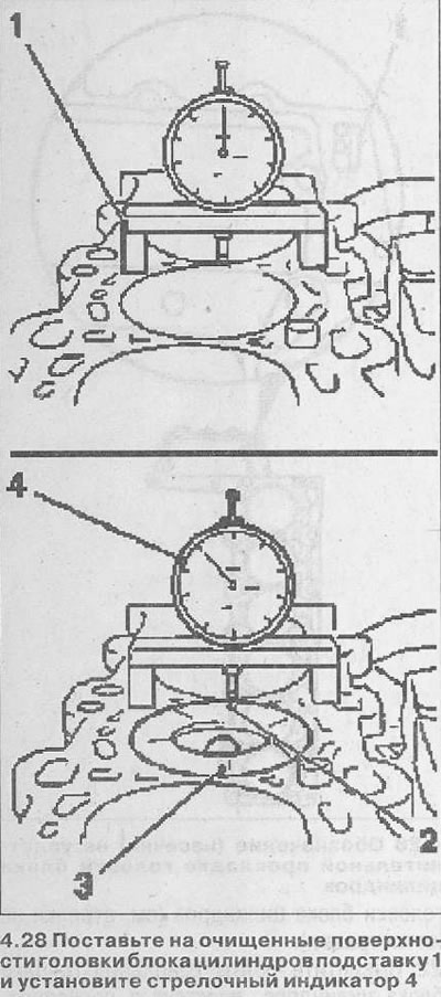
28. Place a stand 1 on the cleaned surfaces of the cylinder head and install a dial indicator 4 to measure the protrusion of the pistons (see illustration).
29. Set the indicator needle to zero.
30. Measure the protrusion of each piston at two points (2 and 3), shifting the stand with the dial indicator accordingly and rotating the crankshaft (see illustration 4.28).
Attention! After determining the protrusion of the pistons, the engine should be fixed at the TDC of the piston of cylinder No. 1.
Selection Chart for Cylinder Head Gasket

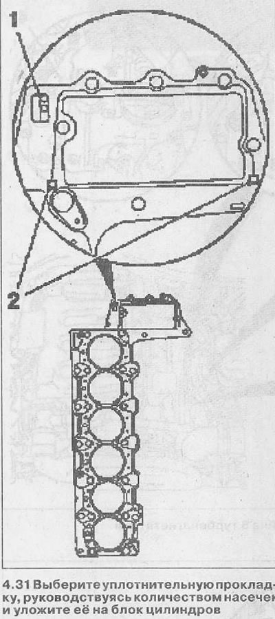
31. Select a sealing gasket, guided by the number of notches and lay it on the cylinder block. It is not necessary to apply sealant, because an additional seal 2 is on the gasket itself (see illustration).
32. Establish a head on the block of cylinders and screw in new bolts of fastening of a head.
33. Tighten the cylinder head bolts in the reverse order of their unscrewing, i.e. 14-1 (see illustration).
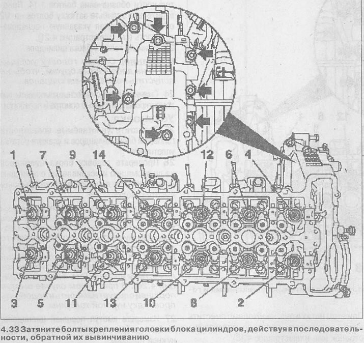
Bolts are tightened in several passes:
- 1st pass. Tighten the bolts to 80 Nm.
- 2nd pass. Loosen the tightening by unscrewing the bolts by 180°.
- 3rd pass. Tighten the bolts to 50 Nm.
- 4th pass. Tighten the bolts by 90°.
- 5th pass. Tighten the bolts by 90°.
34. Unscrew and tighten the bolts securing the timing cover and cylinder head (see arrows in illustration 4.33). The bolts are tightened with a force of 22 Nm.
35. Reinstall the chain guide by tightening the mounting bolt to 20 Nm.
36. Install the chain tensioner by tightening the mounting bolt with a force of 20 Nm.
37. Lubricate the turbocharger mounting bolts with a special black sealant, install a new gasket on the exhaust manifold and secure the turbocharger by tightening the mounting bolt with a force of 50 Nm.
38. Install the turbocharger mounting bracket. Bolt tightening torque 24 Nm.
39. Connect the plugs to the coolant temperature sensor and the preheater.
40. Connect the cooling hoses to the flange on the cylinder head.
41. Install the pressure chamber on the cylinder head by tightening the bolts to 24 Nm.
42. Connect the plug to the pressure sensor in the pressure chamber.
43. Connect the pressure pipe to the injection pump and the pressure chamber. Tightening torque of union nuts 20 Nm.
44. Attach the engine lifting lugs to the cylinder head. The eye bolts are tightened with a force of 24 Nm.
45. Install the exhaust gas recirculation cooler and secure it with 18.8 Nm.
46. Connect the cooling hose to the radiator and secure the radiator with a clamp with a force of 8 Nm.
47. Install hydraulic tappets and camshafts.
48. Install the cylinder head cover.

Visitor comments