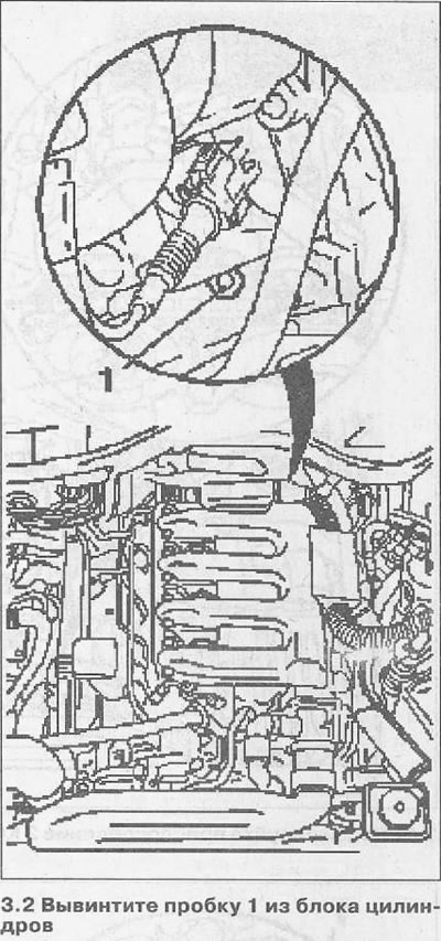
2. Unscrew plug 1 from the cylinder block (see illustration).
3. Turn the crankshaft in the direction of engine rotation by the vibration damper fastening bolt on the belt pulley so that the stop pin 1 KM-813 can be inserted into the hole on the drive disk / flywheel (see illustration). At TDC of the piston of cylinder No. 1, the cams of the piston valve actuator must face each other (see illustration 3.4).
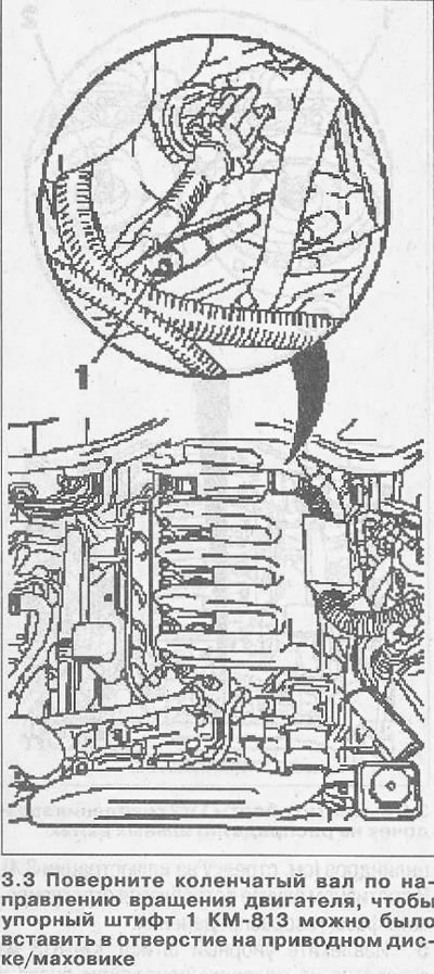
Attention! For vehicles with automatic transmission, it is not allowed to install the thrust pin into the recesses of the torque converter mounting bolts.
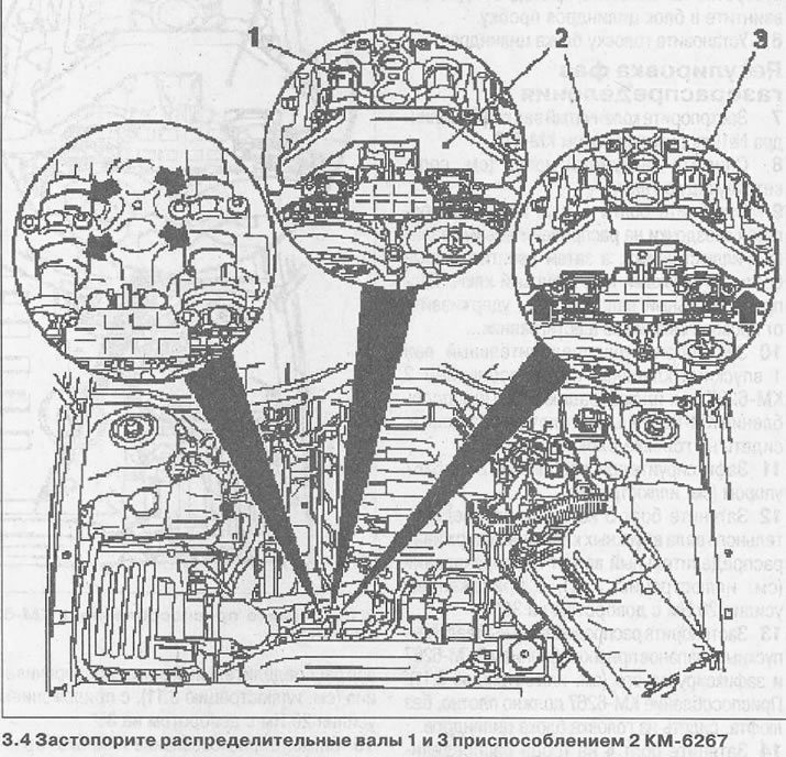
4. Lock camshafts 1 and 3 with tool 2 KM-6267 (see illustration). The KM-6267 fixture should sit snugly, without play, on the cylinder head (see arrow in illustration 3.4). Otherwise, you will need to adjust the valve timing.
5. Remove the thrust pin KM-813 from the hole on the flywheel / drive disk and screw the plug into the cylinder block.
6. Install the cylinder head.
Valve timing adjustment
7. Lock the crankshaft at the TDC of cylinder No. 1 with the thrust pin KM-813.
8. Remove the vacuum pump (see relevant chapter).
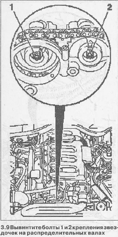
9. Unscrew the bolts 1 and 2, which fasten the sprockets on the camshafts (see illustration), and then install new socket head cap screws. At the same time, hold the camshaft from turning by the hexagon.
10. Lock the camshaft 1 of the inlet valves with tool 2 KM-6267 (see illustration 3.4). The KM-6267 fixture should sit snugly, without play, on the cylinder head.
11. Fix fixture 2 KM-6267 with stop (see illustration).
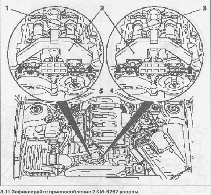
12. Tighten bolt 5 at the end of the intake camshaft, holding the camshaft from turning (see illustration 3.11), with a force of 20 Nm with a turn of 35°.
13. Lock the camshaft 3 of the exhaust valves with tool 2 KM-6267 and fix it (see illustration 3.11). The KM-6267 fixture should sit snugly, without play, on the cylinder head.
14. Tighten bolt 4 at the end of the exhaust camshaft, holding the camshaft from turning (see illustration 3.11), with a force of 20 Nm with a turn of 35°.
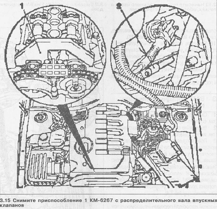
15. Remove tool 1 KM-6267 from the camshafts (see illustration).
16. Remove thrust pin 2 KM-813 from the hole on the flywheel/drive plate.
17. Turn the crankshaft for the vibration damper mounting bolt on the accessory drive belt pulley two turns (720°) in the direction of engine rotation and reinsert the stop pin KM-813 into the hole on the flywheel/drive plate.
Attention! For vehicles with automatic transmission, it is not allowed to install the thrust pin into the recesses of the torque converter mounting bolts.
18. Re-fix the camshafts with the thrust device KM-6267 and make sure that the devices fit tightly on the cylinder head and there is no play between their thrust surfaces (see arrows in illustration).
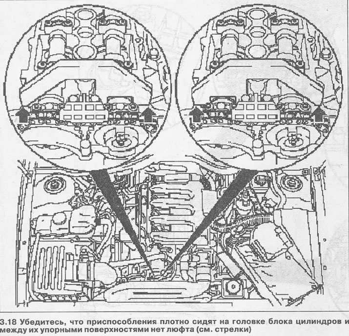
If so, then the valve timing is set correctly.
19. Remove the thrust devices from the shafts and remove the thrust pin that locked the crankshaft.
20. Screw the plug into the cylinder block, reinstall the vacuum pump and cylinder head.

Visitor comments