Attention! The procedure for removing the engine from the engine compartment and its installation is given on the example of a car with a Y22DTH engine and a manual transmission. Removal and installation of other types of engines are carried out similarly.
All wires and other removable parts when dismantling the engine should be laid and secured in the same way as they were located before they were disconnected.
Removing
1. Set the steering wheel to the straight ahead position and remove the key from the ignition.
Cars with air conditioning
2. Disconnect the air conditioning compressor and secure it to the body without disconnecting the pipelines and hoses from it.
Attention! All work on the air conditioning system should be entrusted to a specialized workshop.
3. Unscrew the mounting bolts and remove the mudguard (protection) 1 engine compartment (see illustration).
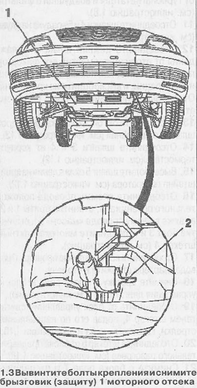
4. Drain the coolant into a container by unscrewing the drain plug 2 on the radiator (see illustration 1.3).
5. Disconnect and remove the pipes of the exhaust system (see relevant chapter).
6. Remove cardan shaft.
4x4 vehicles
7. Remove cover 6 of the cylinder head by unscrewing the mounting bolts.
8. Disconnect the cooling hose 1 from the air supply duct, as well as the plug 3 of the mass air flow sensor (see illustration).
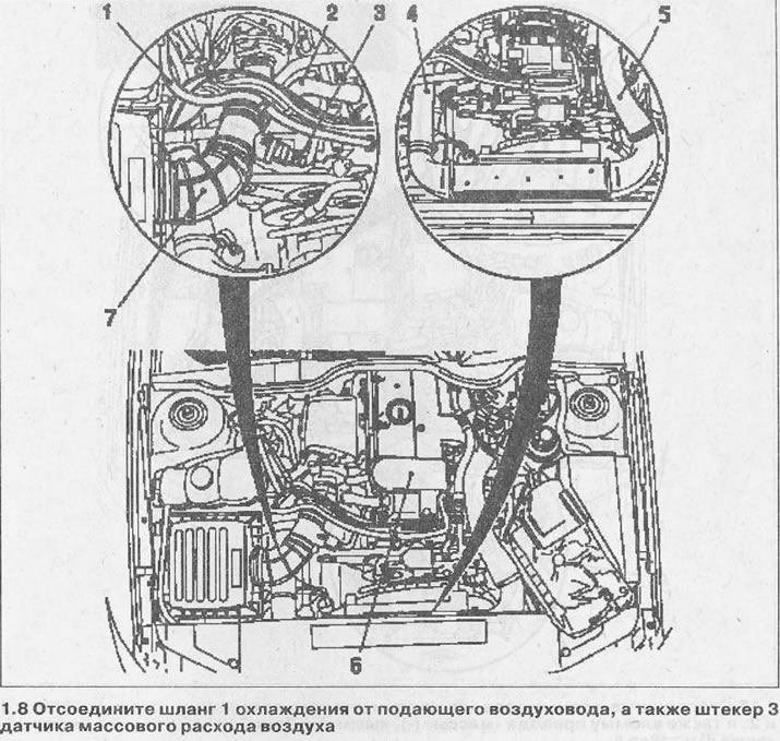
9. Disconnect the crankcase ventilation hose 2 from the cylinder head cover (see illustration 1.8).
10. Disconnect the charge air hose 7 from the turbocharger and air filter (see illustration 1.8).
11. Disconnect hoses 4 and 5 of charge air (see illustration 1.8).
12. Disconnect the lower cooling hose 1 from the heater by moving its retainer in the direction as shown by the arrow in the illustration, and release it from the fasteners. Set the disconnected hose away from the work site.
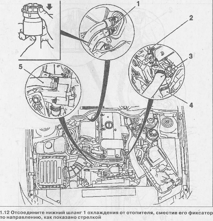
13. Disconnect the cooling hose 2 from the cylinder head (see illustration 1.12).
14. Disconnect hoses 3 and 4 from the thermostat housing (see illustration 1.12).
15. Release the cooling hose 5 from the generator bracket (see illustration 1.12).
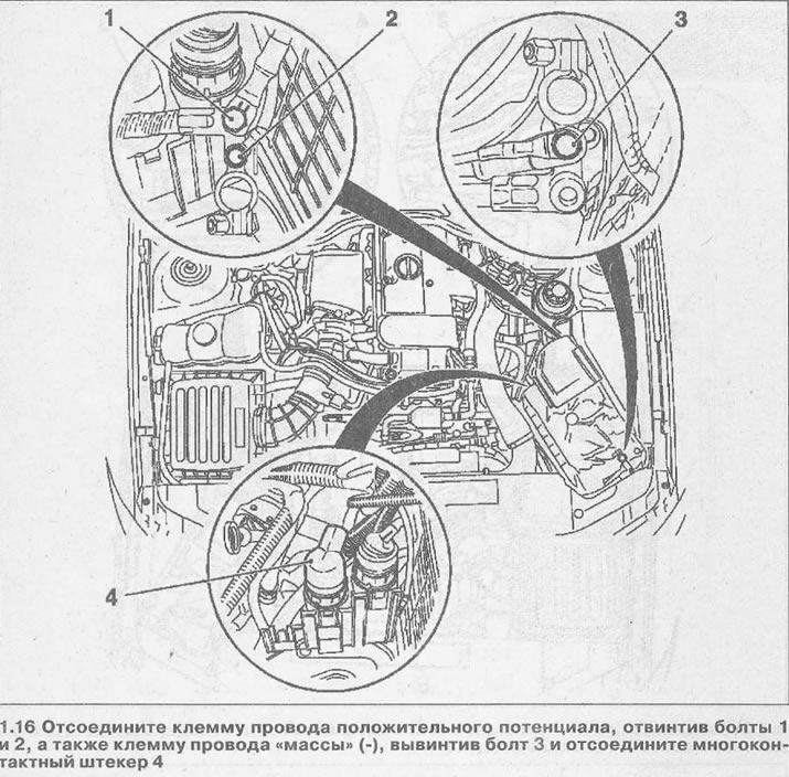
16. Disconnect the positive potential wire terminal by unscrewing bolts 1 and 2, as well as the wire terminal «masses» (-), unscrew the screw 3 and disconnect the multi-pin plug 4 (see illustration).
17. Disconnect all other wires. Set the starter wires aside.
18. Remove the cover 9 of the relay unit and the engine control unit 4 (see illustration).
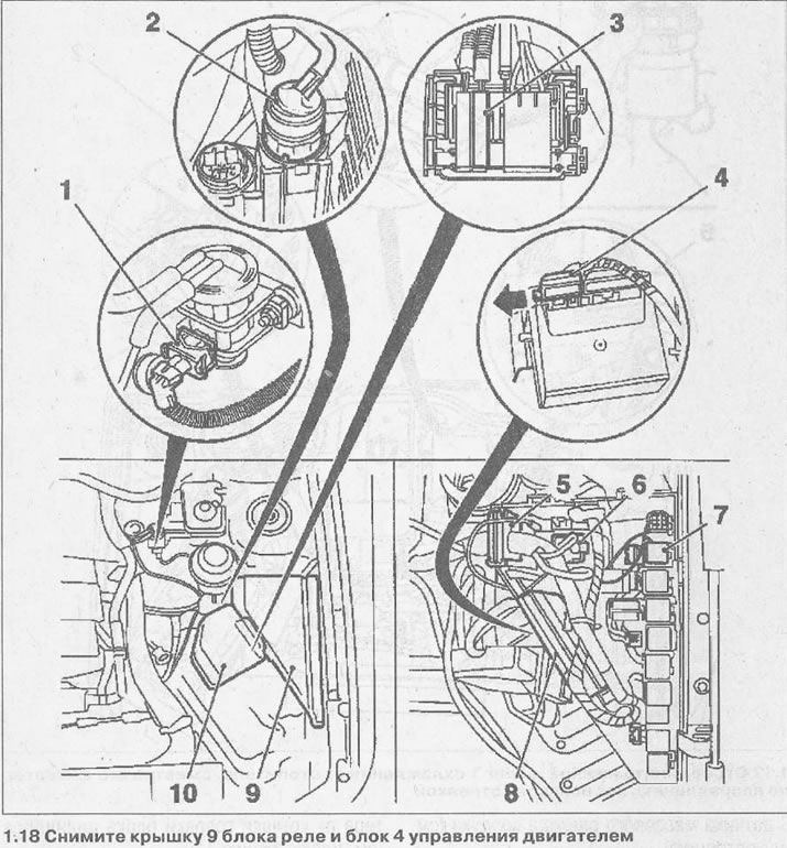
19. Disconnect plug 4 from the engine control unit by pushing it in the direction of the arrow, as shown in illustration 1.18.
20. Disconnect plug 6 from the preheating unit (see illustration 1.18).
21. Remove from the relay block 7 and disconnect the multi-pin plug 2 (see illustration 1.18).
22. Remove cover 10 from the fuse box and remove fuse 3 (see illustration 1.18).
23. Disconnect the plug 1 of the EGR solenoid valve (see illustration 1.18).
24. Release the engine wiring harness from the mount on the relay box along with the rubber grommet 5 and set it aside (see illustration 1.18).
25. Disconnect the hose 1 of the brake booster from the vacuum pump by pressing the latch (see arrow in illustration).
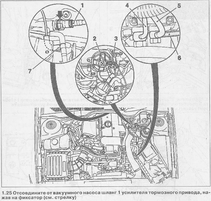
26. Disconnect hoses 2 and low pressure supply to the membrane valve of the exhaust gas recirculation system (see illustration 1.25).
27. Disconnect the low pressure hose 7 from the T-piece (see illustration 1.25).
28. Disconnect the fuel return hose 6 from the fuel return line (see illustration 1.25).
29. Disconnect the supply 4 and return fuel lines from the injection pump (see illustration 1.25).
30. Release the fuel lines from the mounting on the cylinder head cover and set them aside.
31. Take the fluid from the reservoir 5 of the power steering (see illustration).
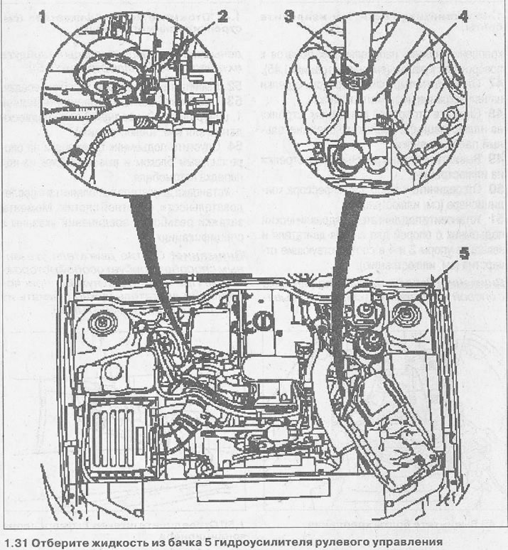
32. Disconnect the pressure pipes 3 and 4 from the power steering pump, collecting the liquid flowing from them (see illustration 1.31).
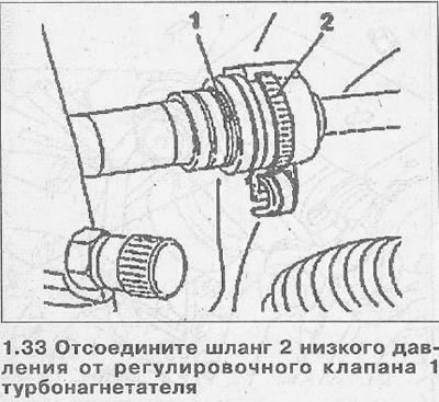
33. Disconnect the low pressure hose 2 from the turbocharger control valve 1 (see illustration).
34. Fill the brake fluid reservoir completely and close the cap.
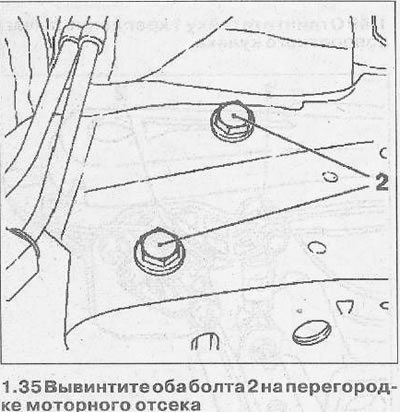
35. Unscrew both bolts 2 on the bulkhead of the engine compartment (see illustration).
36. Wring out a clamp and disconnect the pipeline of a drive of coupling. Return the clamp after disconnecting the pipeline to its original position.
37. Unscrew wheel bolts and remove forward wheels.
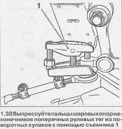
38. Unscrew the nuts of the ball bearings of the tie rod ends and press out the pins of the tie rod bearings from the steering knuckles using a puller 1 (see illustration).
39. Loosen the intermediate bracket mounting bolts. The bolts must not be completely unscrewed.
40. Remove the cap from the nut 1 fastening the steering knuckle lever and unscrew the nut (see illustration).
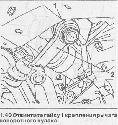
41. Press out the finger of the lever 2 of the steering knuckle using the KM-146-01 puller (see illustration 1.40).
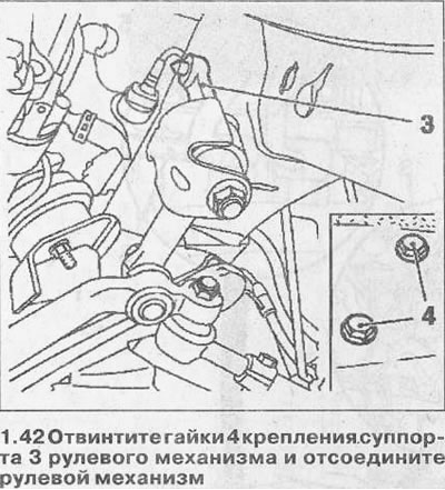
42. Unscrew the nuts 4 fastening the caliper 3 of the steering gear and disconnect the steering gear (see illustration).
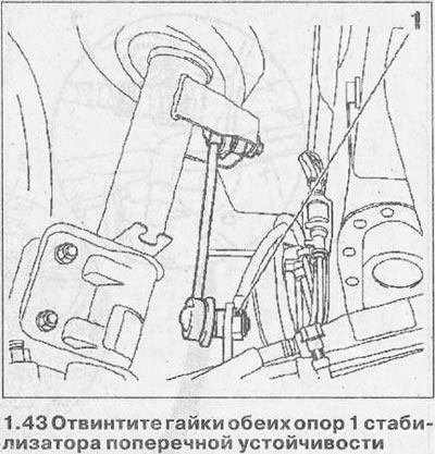
43. Unscrew the nuts of both supports 1 of the anti-roll bar (see illustration).
44. Cars with xenon headlights. Disconnect connector 2 for ride height sensor and unscrew ball joint pin 3 (see illustration).

45. Unscrew the nuts 1 and remove the bolts (see illustration).
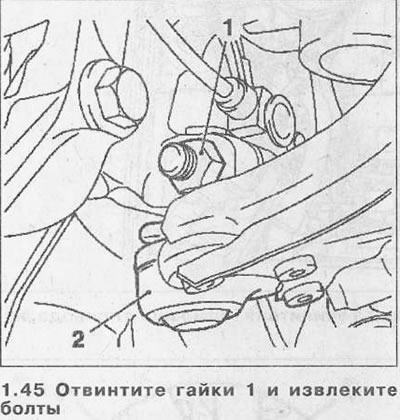
46. Press out the fingers of the ball bearings 2 fastenings of the lower guide levers to the steering knuckles (see illustration 1.45).
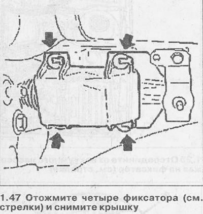
47. Press out the four latches (see arrows in illustration) and remove the cover.
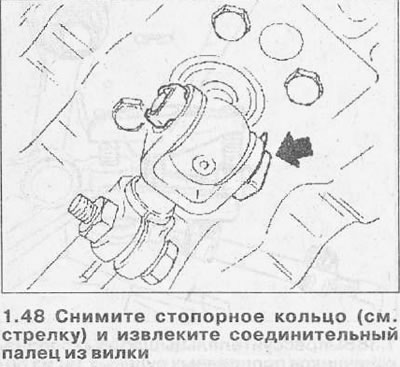
48. Remove retaining ring (see arrow in illustration) and remove the connecting pin from the plug.
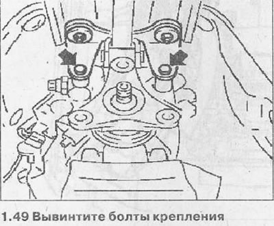
49. Unscrew the mounting bolts (see arrows in illustration).
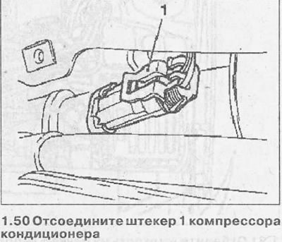
50. Disconnect the plug 1 of the air conditioning compressor (see illustration).
51. Place a hydraulic lift under the engine with a support for removing the engine and insert stops 2 and 4 into the corresponding holes (see illustration).
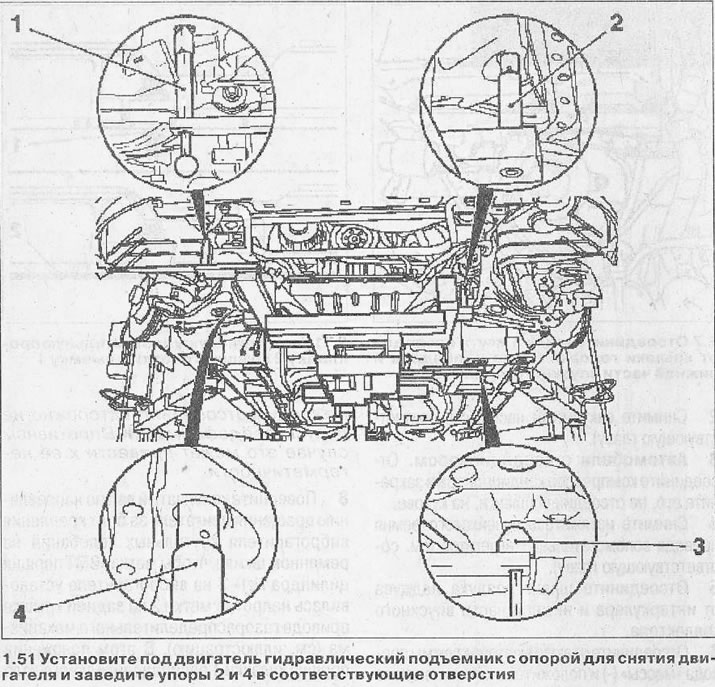
Attention! Before installing the lift with the support, make sure that the supports 1 and 3 are out and the centering pins will not go into their holes (see illustration 1.51).
52. Unscrew bolts of a support of a transmission.
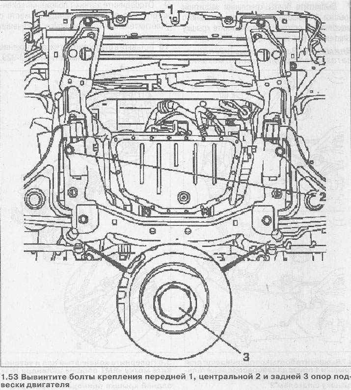
53. Unscrew the bolts of the front 1, center 2 and rear 3 engine mounts (see illustration).
54. Lower the lift with the power block lying on the support and take the block out from under the front of the car.
The engine is installed in the reverse order of removal. The tightening torques for threaded connections are specified in specifications.
Attention! Removing the engine in this way requires special care. In the absence of the necessary devices, the engine must be removed from the engine compartment with a beam crane.

Visitor comments