Removing
Attention! The cylinder head should only be removed from a cold engine.
1. Cars with air conditioning. Disconnect the A/C compressor and secure it to the body without disconnecting the refrigerant hoses/pipes from the compressor.
Attention! All work relating to the removal, installation of the air conditioner, draining and refilling the refrigerant should be entrusted to a specialized workshop.
2. Remove the windshield wiper motor (see relevant chapter).
3. Unscrew the mounting bolts and remove the cylinder head cover (see relevant chapter).
4. Remove the vacuum pump (see relevant chapter).
5. Remove the accessory drive belts.
6. Remove the accessory drive belt tensioner.
7. Set the piston of cylinder No. 1 to TDC and lock the camshaft with the KM-932 fixture, and the high-pressure fuel pump with the KM-927 thrust pin.
8. Disconnect plug 3 from the mass air flow sensor and hoses 5 from the air filter and turbocharger (see illustration).
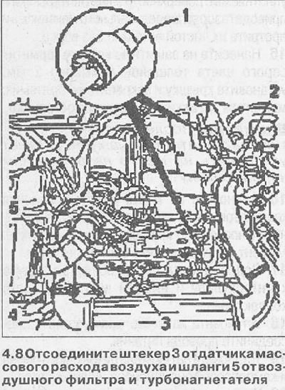
9. Disconnect both hoses 2 and 4 of charge air (see illustration 4.8).
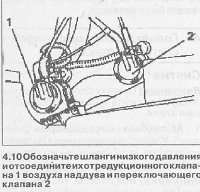
10. Label the low pressure hoses and disconnect them from the boost air pressure reducing valve 1 and changeover valve 2 (see illustration).
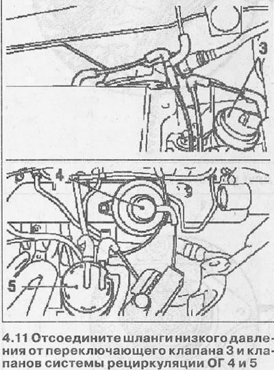
11. Disconnect the low pressure hoses from switchover valve 3 and EGR valves 4 and 5 (see illustration).
12. Disconnect fuel return line 2 from fuel injector rail and fuel supply line (see illustration).
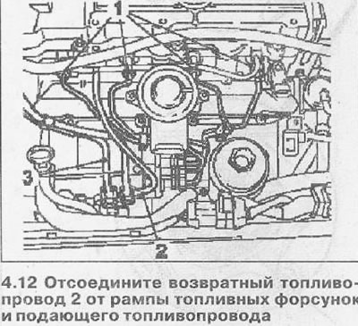
13. Disconnect the fuel lines 3 from the injection pump and take them away from the place of work (see illustration 4.12).
14. Disconnect the high pressure fuel lines 1 from the injector rail and from the injection pump (see illustration 4.12).
15. Remove the mounting bolts and remove the heat shield from the turbocharger and exhaust manifold.
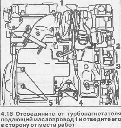
16. Disconnect the oil supply line 1 from the turbocharger and take it away from the place of work (see illustration). Collect the leaked engine oil.
17. Disconnect from a final collector a reception pipe.
18. Vehicles with Y22DTH engine. Remove the catalyst from the turbocharger.
19. Unscrew the bolts 5 and unscrew the nut 4 fastening the heat shield of the starter (see illustration 4.16).
20. Disconnect the oil return line 2 from the cylinder block (see illustration 4.16).
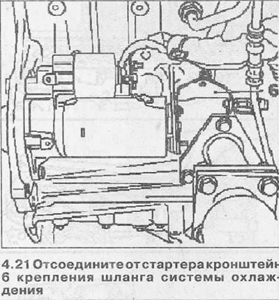
21. Disconnect from the starter the bracket 6 for fastening the cooling system hose (see illustration).
22. Unscrew the mounting bolts and disconnect the exhaust manifold mounting bracket 3, and then turn its side by loosening the mounting bolt on the cylinder block (see illustration 4.16).
23. Unscrew the plug from the drain hole on the radiator and drain the coolant.
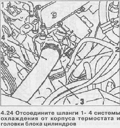
24. Disconnect hoses 1-4 of the cooling system from the thermostat housing and cylinder head (see illustration).
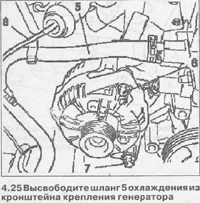
25. Release the cooling hose 5 from the generator mounting bracket (see illustration).
26. Vehicles with X20DTH engine.
Disconnect the low pressure hose 8 from the boost air pressure reducing valve (see illustration 4.25).
27. Vehicles with Y22DTH engine.
Disconnect the low pressure hose from the supercharger vane position control valve.
28. Loosen the lower bolt 7 of the generator, unscrew the top 6 and move the generator to the side (see illustration 4.25).
29. Mark the mounting position of the timing chain tensioner 2 and remove it (see illustration).
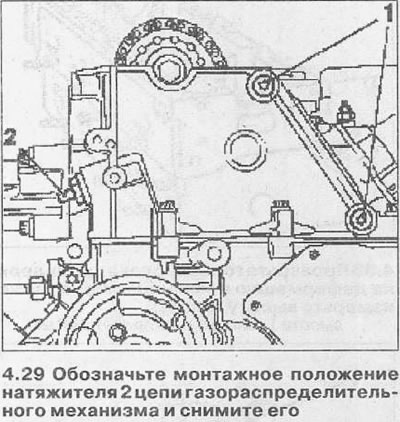
30. Heat the bolts 1 that secure the guide with a hair dryer (sedative) timing chains and unscrew them (see illustration 4.29).
Attention! Use a suitable heat shield to prevent damage to the chain guide when the bolts are heated.
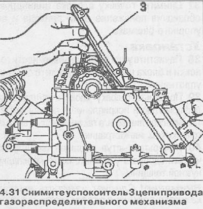
31. Remove the damper 3 of the timing chain by pushing it up. Before removing, mark its installation position (see illustration).
32. Clean the holes for the chain guide bolts in the cylinder block.
33. Remove the KM-932 fixture from the cylinder head and remove the KM-927 thrust pin from the injection pump.
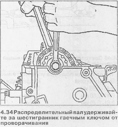
34. Remove the sprocket from the camshaft by unscrewing its fastening bolt. At the same time, hold the camshaft by the hexagon with a wrench from turning (see illustration). Leave the chain removed from the sprockets in the channel of the gas distribution mechanism housing.
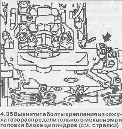
35. Unscrew the mounting bolts from the casing of the gas distribution mechanism and the cylinder head (see arrows in illustration).
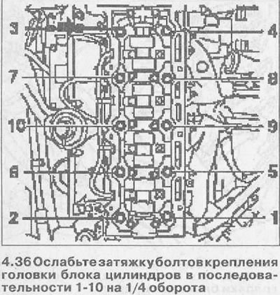
36. Loosen the cylinder head bolts in the sequence 1-10 by ¼ turn, then unscrew them in the same sequence by another ½ turn, and then unscrew completely (see illustration).
37. Remove the head from the cylinder block, marking the position of the drive chain and its thrust shoe.
Installation
38. Clean the sealing surfaces of the cylinder head and block and remove seal residues.
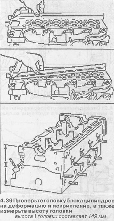
39. Check the cylinder head for deformation and distortion with a metal ruler, and also measure the height of the head (see illustration).
40. Measure the protrusion of the pistons of the cylinders in order to select the sealing gasket of the required thickness.

Attention! The protrusion of each piston should be measured separately.
41. Place a stand 2 on the cleaned surfaces of the cylinder head and install a dial indicator 1 to measure the protrusion of the pistons (see illustration).
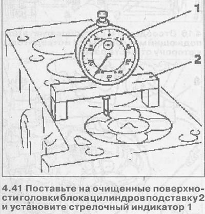
42. Set the indicator needle to zero.
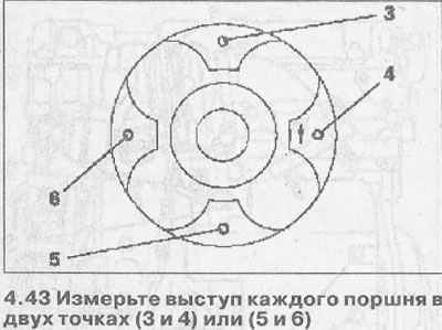
43. Measure the protrusion of each piston at two points (3 and 4) or (5 and 6), shifting the stand with the dial indicator accordingly and rotating the crankshaft (see illustration).
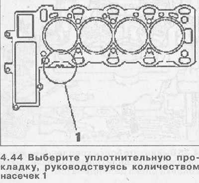
44. Select a sealing gasket, guided by the number of notches 1 and lay it on the cylinder block (see illustration).
45. After measuring the protrusion of the pistons, fix the crankshaft with the thrust pin KM-929, setting the piston of cylinder No. 1 to TDC.
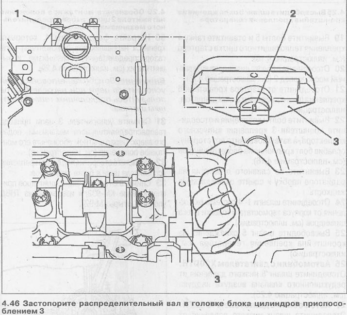
46. Lock the camshaft in the cylinder head with tool 3 KM-932 by inserting its pin 2 into hole 1 (see illustration).
47. Establish a head with the fixed camshaft on the block of cylinders and screw in new bolts of fastening of a head.
Attention! When installing the head on the block, watch the timing chain and its tensioner shoe.
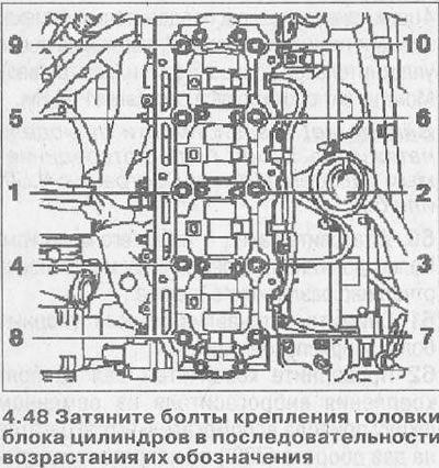
48. Tighten the cylinder head bolts in ascending order of their designations and acting in a spiral manner - from the center to the ends (see illustration). Bolts are tightened in several passes:
- 1st pass. Tighten the bolts to 25 Nm.
- 2nd pass. Turn the bolts by 65°.
- 3rd pass. Tighten the bolts by 65°.
- 4th pass. Tighten the bolts by 65°.
- 5th pass. Tighten the bolts by 65°.
- 6th pass. Tighten the bolts by 15°.
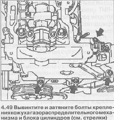
49. Unscrew and tighten the bolts securing the timing cover and cylinder block (see arrows in illustration). The bolts are also tightened in several passes:
- 1st pass. Tighten the bolts with 20 Nm.
- 2nd pass. Rotate the bolts by 30°.
- 3rd pass. Tighten the bolts by 5°.
50. Put the timing chain on the sprocket and secure the sprocket to the camshaft.
51. Secure the sprocket mounted on the camshaft with a new bolt, tightening it by hand.
52. Reinstall the timing chain damper and secure it with new bolts. The tightening torque for the damper bolts is 8 Nm.
53. Make sure that the arrow 1 on the injection pump drive sprocket is opposite the notch and hole 2 on the injection pump flange (see illustration).
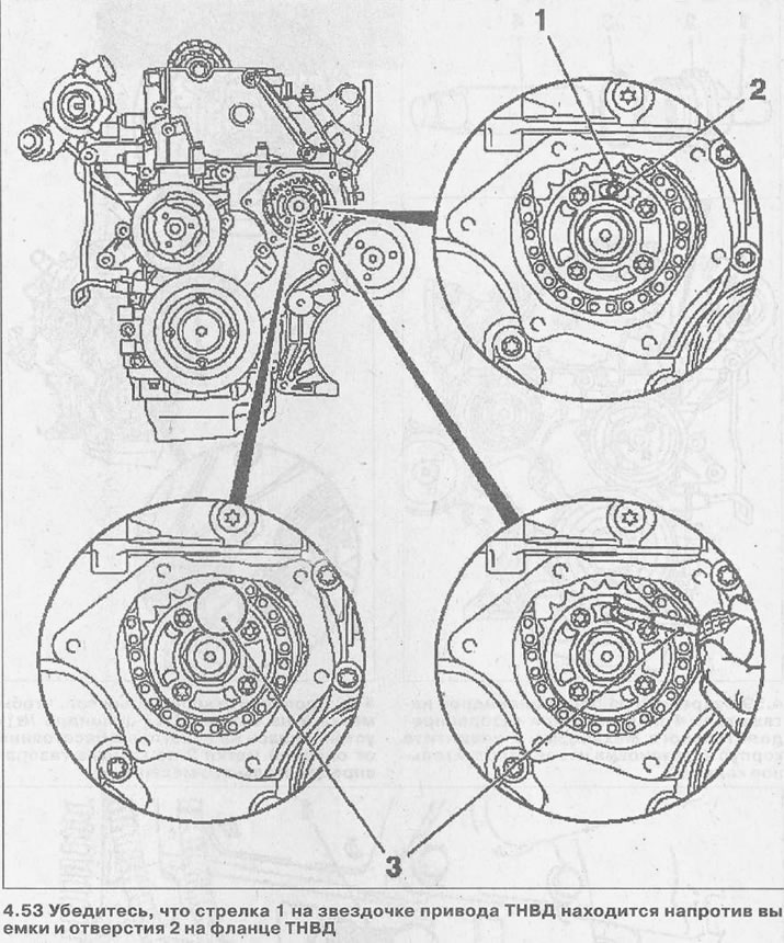
54. Fix the injection pump by inserting a thrust pin 3 KM-927 into the hole in the flange (see illustration 4.53).
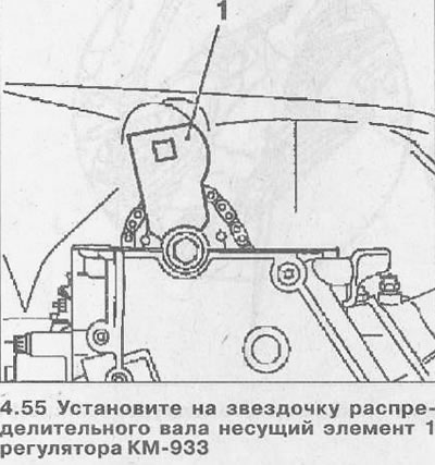
55. Install the carrier element 1 of the KM-933 regulator on the camshaft sprocket so that it is located strictly vertically (see illustration).
56. Fix the support 4 of the KM-933 regulator on the cylinder head (see illustration)
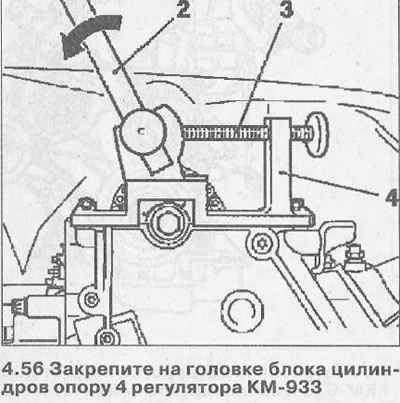
57. Fasten the handle 2 in the hole of the bearing element 1, pull it out in the direction of the arrow and fix the element in this position with the clamping bolt 3 (see illustration 4.56).
58. Tighten the sprocket mounting bolt on the camshaft with a force of 90 Nm, and then tighten it first by 60°and then by 30°.
59. Fix the tensioner 4 of the timing chain on the cylinder block and screw on the housing 2 by installing a new sealing ring 3 (see illustration). The tightening torque for the housing is 60 Nm. Attention! Depending on the model, the tensioner can be with a detachable pin 1 (see illustration 4.59) or without.
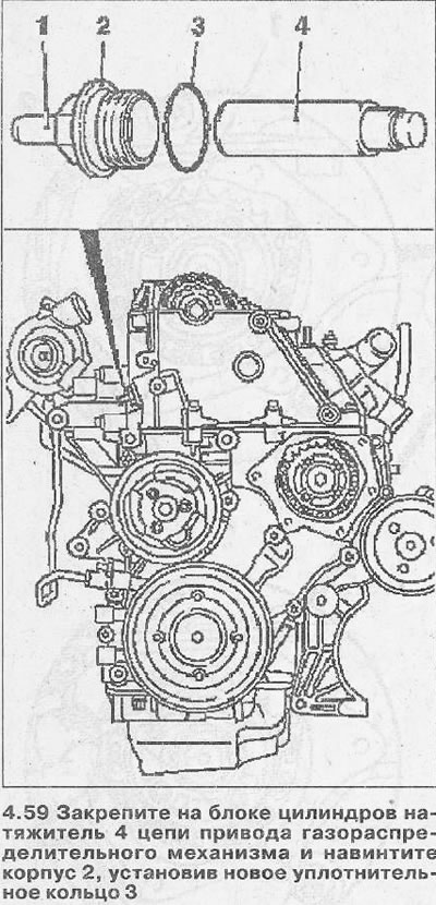
60. Install pin 1 by hammering it. The finger should snap into place with a distinct click.
61. Remove the installed thrust bolts and fixtures.
62. Turn the crankshaft for the vibration damper mounting bolt on the accessory drive belt pulley two turns (720°) in the direction of rotation of the engine so that mark 3 on the pulley «TDC cylinder #1» installed at some distance from the reference mark 2 on the cover of the gas distribution mechanism (see illustration).
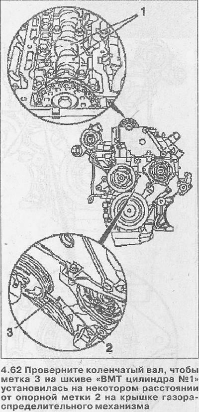
In this position, the cams 1 of the cylinder piston valve drive must be turned up (see illustration 4.62).
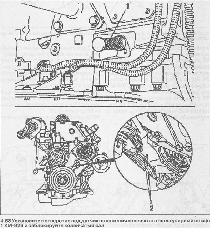
63. Install thrust pin 1 KM-929 in the hole for the crankshaft position sensor and block the crankshaft (see illustration). If necessary, turn the crankshaft slightly in the direction of engine rotation to achieve the desired seating of the thrust pin.
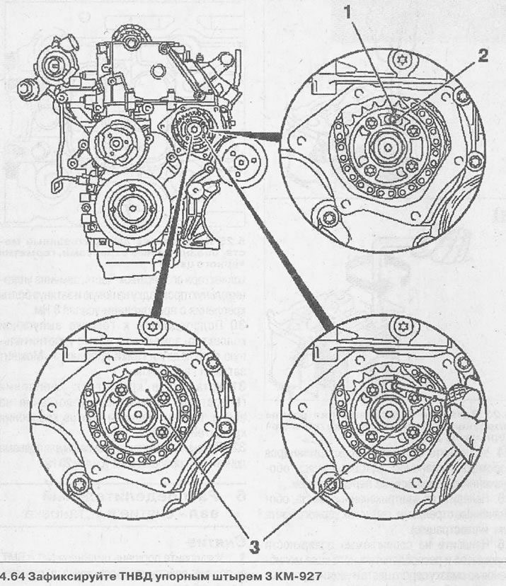
In this position of the crankshaft, reference marks 2 must be opposite each other (see illustration 4.63), and the arrow 1 on the injection pump sprocket - coincide with the notch and hole 2 on the flange (see illustration 4.64).
64. Fix the injection pump with a thrust pin 3 KM-927, inserting it into the hole on the flange of the drive sprocket (see illustration).
65. Fix the camshaft using tool 3 KM-932, fixing it on the cylinder head and inserting its thrust pin 2 into hole 1 of the camshaft flange (see illustration 4.46).
Attention! If the thrust pin 2 of the KM-932 device cannot be inserted into the hole on the flange and thus fix the camshaft, then the procedure for adjusting the valve timing should be completely repeated.
Further installation of the cylinder head is carried out in the reverse order of removal. The tightening torques for the respective screw connections are given in specifications.

Visitor comments