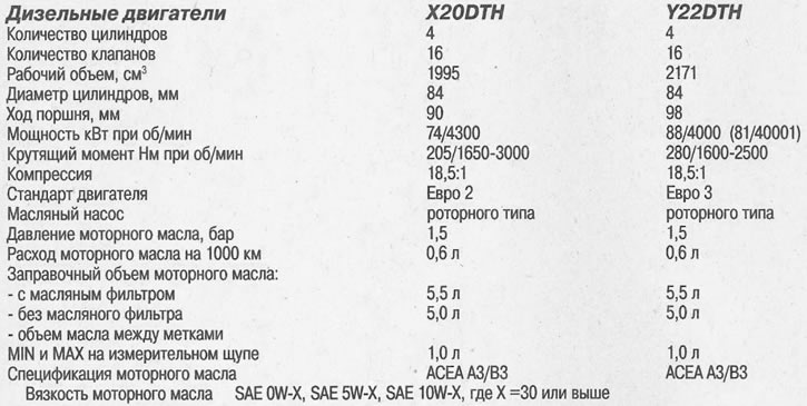
Tightening torques for threaded connections, Nm
- Bolts of fastening of a cover of the block of damping of torsional fluctuations — 8
- Starter mounting bolts - 45
- Exhaust manifold to cylinder head - 22
- Damper tensioner ribbed belt - 20
- Damper tensioner ribbed belt to the tensioner - 20
- Differential cover - 20 + turn 30°
- Oil filter cap - 25
- Oil pump cover - 8
- Timing gear cover - 6
- Vibration damper - 150 + turn by 45°and 15°
- Engine oil level sensor - 8
- Lower part of the oil pan - 8
- The lower part of the intake manifold to the cylinder head - 22
- Fuel line to injection pump - 30
- Fuel line to the injector rail - 30
- High pressure fuel pump to cylinder block - 25
- Accelerator pedal to bulkhead - 20
- Swivel fist - 65
- Chain guide on vibration damping unit - 9
- The damper of the double timing chain to the cylinder block - 8
- Single-row damper for the timing chain to the cylinder block - 8
- Coolant temperature sensor to thermostat housing - 10
- Rack to the stabilizer bar - 100
- Generator to bracket - 35
- Alternator Bracket - 35
- Oil pan, bolts M10 - 40
- Transmission to the block of cylinders. Bolts M12 - 60
- Transmission to the bottom - 45
- Glow plugs - 10
- Auxiliary Bracket - 35
- Starter bracket to cylinder block - 25
- Bracket injection pump to injection pump - 20
- Bracket injection pump to the cylinder block - 20
- Engine support bracket to cylinder block - 60
- Heat shields - 8
- Pressure oil lines to the power steering pump - 37.5
- Crankshaft position sensor to cylinder block - 8
- Ribbed belt tensioner to bracket - 42
- Asterisk to the vibration damper shaft - 90 + 30
- Vibration damping chain tensioner - 9
- Fuel line to injection pump - 15
- Main bearing cap bolts - 90 + 60°and 15°turn
- Water pump in the casing of the timing gear drive - 20
- Engine mount to bracket - 40
- Engine mount to subframe - 55
- Camshaft bearing caps to cylinder head - 15
- Camshaft sprocket to shaft - 90 + turn by 60°and 30°
- Drain plug at the bottom of the oil pan -: - 10
- Engine Oil Pressure Sensor - 30
- Turbocharger oil return line to cylinder block - 20
- Oil supply line to the turbocharger - 20
- The lower part of the oil pan to the transmission - 20
- The upper part of the oil pan to the casing of the gas distribution mechanism drive - 20
- The lower part of the oil pan to the cylinder block - 20
- Connecting rod bearing cap bolts - 35 + 45°and 15°turn
- Wheel bolts - 110
- Water pump pulley - 20
- Flywheel to crankshaft - 45 + turn by 30°and 15°
- Coolant temperature sensor to cylinder head - 18
- Boost air pressure sensor - 8
- Engine oil temperature sensor - 18
- High pressure fuel pump to flange - 28
- The tip of the transverse tie rod to the steering knuckle - 60
- Tie rod - 60
- Casing of a drive of the gas-distributing mechanism to the block of cylinders — 20
- Exhaust manifold bracket to manifold and cylinder block - 25
- Thermostat housing - 8
- Turbocharger to exhaust manifold - 30
- Chain tensioner to the casing of the gas distribution mechanism - 60
- Front engine mount - 65 + turn by 30°and 15°
- Central engine support - 150 + turn 30°and 15°
- Rear engine mount - 130 + turn 30°and 15°
- Cylinder head to timing gear housing - 20 + 30°and 5°turn
- Head to cylinder block - 25 + turn by 65°+ 65°+ 65°+ 15°
- Cylinder head cover - 8
Cylinder head and valves (see illustration 0.0)
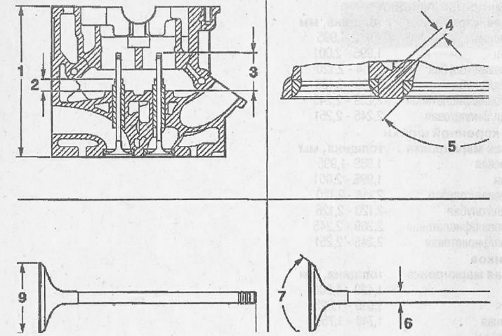
0.0 Cylinder head and valves
1 - cylinder head height
2 - protrusion of the valve guide
3 - protrusion of the valve stem
4 - the width of the valve seat in the cylinder head
5 - the angle of the seat chamfer of the valve seat in the cylinder head
6 - valve stem diameter
7 - chamfer angle of the valve seat
8 - valve stem length
9 - valve disc diameter
Cylinder head height, mm - 140
Width of a landing saddle of the valve in a head of the block of cylinders, mm
- intake valves - 1.4 -1.8
- exhaust valves - 1.4 -1.8
The angle of the landing chamfer of the valve seat in the cylinder head is 90°
Valve guide diameter, mm
- nominal size - 6.000 - 6.012
- 1st repair size (0,075) — 6,075 - 6,090
- 2nd repair size (0,150) — 6,150 - 6,165
Valve guide length, mm
- intake valves - 44.75 - 45.25
- exhaust valves - 34.75 - 35.25
Valve guide protrusion, mm
- intake valves - 11.2-11.5
- exhaust valves - 11.2 -11.5
Valve stem protrusion, mm nominal size - 37.0 - 37.6
- 1st repair size (0,075) — 36,6 - 37,2
- 2nd repair size (0,150) — 36,6 - 37,2
Valve stem length, mm
nominal size
- intake valves - 96.90 - 97.30
- exhaust valves - 96.90 - 97.30
1st repair size (0,075)
- intake valves - 96.50 - 96.90
- exhaust valves - 96.50 - 96.90
2nd repair size (0,150)
- intake valves - 96.50 - 96.90
- exhaust valves - 96.50 - 96.90
Valve stem diameter, mm
nominal size
- intake valves - 5.955 - 5.970
- exhaust valves - 5.945 - 5.960
1st repair size (0,075)
- intake valves - 6.030 - 6.045
- exhaust valves - 6.020 - 6.035
2nd repair size (0,150)
- intake valves - 6.105 - 6.120
- exhaust valves - 6.095-6.110
Valve stem clearance, mm
- intake valves - 0.030 - 0.057
- exhaust valves - 0.040 - 0.067
Permissible ovality of the valve stem, mm - 0.03
Valve disc diameter, mm
- intake valves - 29.0
- exhaust valves - 26.0
The angle of the landing chamfer of the valve seat in the cylinder head - 90°40'
Attention! Grinding of the cylinder head is not permitted.
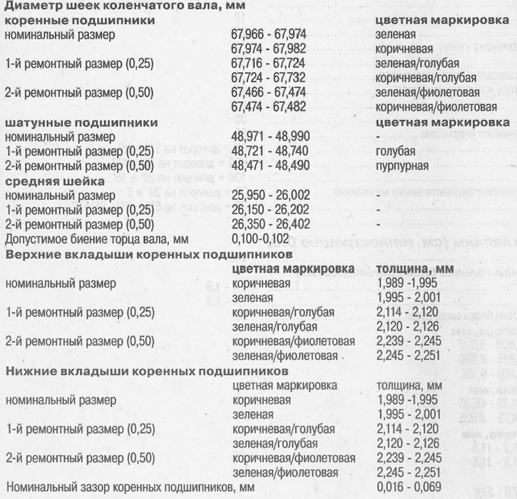
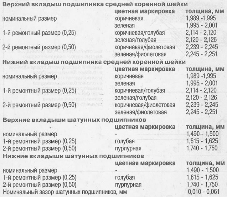
Crankshaft (see illustration 0.0a)
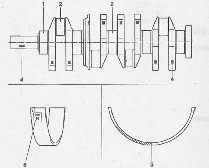
0.0a Crankshaft
1 - journals of main bearings
2 - necks of connecting rod bearings
3 - the neck of the middle main bearing
4 - color marking
5 - color marking of liners
6 - designation of liners
Cylinder block (see illustration 0.0b)
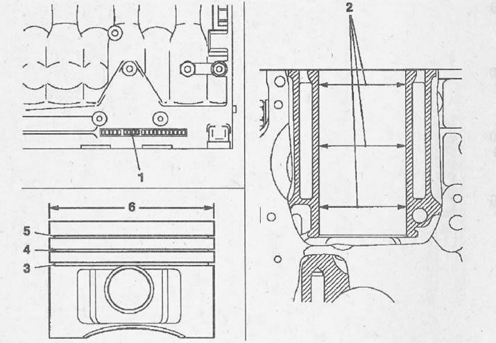
0.0b Cylinder block
1 - cylinder class
2 - cylinder bore diameter
3 - oil scraper ring with expansion spring
4 - lower compression ring
5 - top trapezoidal compression ring
6 - piston diameter
Cylinder bore diameter - nominal size, mm
- class 8 - 83.975-83.985
- class 99 - 83.985-83.995
- class 00 - 83.995-84.005
- class 01 - 84.005-84.015
- class 02 - 84.015-84.025
Increased size after boring, mm - 84.465 -84.475
Cylinder piston diameter - nominal size, mm
- class 8 - 83.885-83.895
- class 99 - 83.895-83.905
- class 00 - 83.905-83.915
- class 01 - 83.915-83.925
- class 02 - 83.925-83.935
Increased size, mm - 84.375 -84.385
Clearance between the cylinder mirror and the piston, mm - 0.08 - 0.10
Piston protrusion, mm - 0.50-0.70
Piston rings, mm
top compression ring
- thickness - 2.50
- lock clearance - 0.25-0.50
- clearance between grooves - 0.08 -0.12
lower compression ring
- thickness - 1.75
- lock clearance - 0.25-0.50
- clearance between grooves - 0.05-0.09
oil scraper ring
- thickness - 3.00
- lock clearance - 0.25-0.50
- gap between grooves - 0.03-0.07
Piston pin
- length, mm - 68
- diameter, mm — 29

Visitor comments