Attention! On models with a 6-cylinder engine with air conditioning, it is necessary to disconnect the coolant-carrying pipes in order to be able to remove the engine block from the vehicle (see related section). Contact an air conditioner specialist to discharge the system. And only after that you can start working. Have various caps/plugs ready to plug the hoses/joints while removing the engine. In conclusion, it is necessary to charge the air conditioner system (contact a specialist). Do not turn on the air conditioning system while it is discharged.
Removing
1. Park the car on a level ground, then remove the hood (see related section).
2. Remove the battery (see related section).
3. Block the rear wheels, then apply the handbrake. Jack up the front of the vehicle and support it securely with axle stands. Loosen the mounting screws and remove the bottom cover from under the engine.
4. Drain the liquid from the cooling system (see related section). If the engine needs to be disassembled, also drain the engine oil and remove the oil filter.
5. Depressurize the fuel system (see related section), then remove the engine control module.
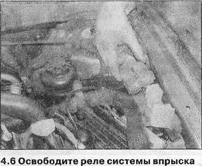
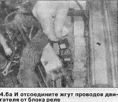
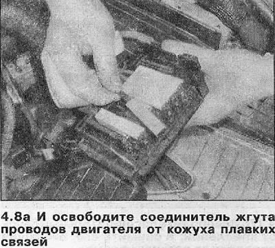
6. Remove the cover from the relay box in the engine compartment, and trace the wiring harness from the engine to the box. Release the injection system relay, then disconnect the engine wiring harness connector from the relay box (see illustrations). Loosen the o-ring and pull the harness away from the relay box.
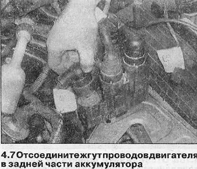
7. Disconnect the engine wiring harness that is installed at the rear of the battery (see illustration).
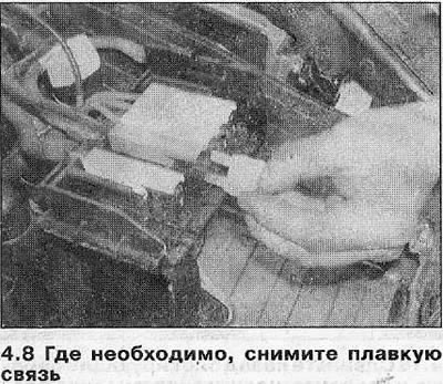
8. Disconnect the engine harness auxiliary connector from the positive battery terminal, and unscrew the ground strap from the front of the engine. On some models, the harness is connected to the fuse box instead of the battery terminal; in this case, remove the fusible link, and release the connector from the casing (see illustrations). Then proceed as described in the corresponding sub-heading.
Cars with 4-cylinder engine
9. Proceed as described in Section 4A, perform the following procedures:
- A) Remove the air filter cover and intake ducts.
- b) Remove the throttle body.
- V) Remove the muffler intake pipe.
- G) Disconnect the supply and return fuel hoses from the fuel line.
- d) Disconnect the brake booster hose and various vacuum hoses from the intake manifold, noting their location. Also disconnect the hose from the auxiliary air valve on the exhaust manifold.
10. Disconnect the coolant hose from the rear of the coolant pipe on the right side of the engine compartment. Also disconnect the upper radiator hose from the cylinder head and the hose from the ignition module bracket at the rear of the cylinder head.
11. Remove the engine as described in paragraphs 12-19.
Vehicles with a 6-cylinder engine
12. Remove the wiper motor (see related section).
13. Remove the radiator (see related section).
14. Loosen the mounting bracket, and disconnect the upper radiator hose from the coolant pipe on the left cylinder head.
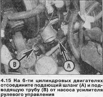
15. Wipe area around hose/pipe couplers on power steering pump (see illustration). Loosen the mounting bracket, then disconnect the supply hose from the pump and drain the reservoir into a suitable container. Loosen the nut and disconnect the supply pipe from the pump, then plug the hose and pump couplings to prevent dirt from entering the system.
16. Acting as described in Section 4A, perform the following procedures:
- A) Remove the air filter cover and intake ducts.
- b) Disconnect the throttle cable and (where necessary) the speed control cable from the throttle link and release them from the bracket.
- V) Remove the exhaust pipes from the muffler.
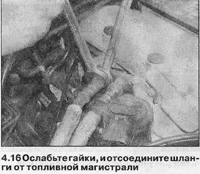
- G) Disconnect the supply and return fuel hoses from the fuel line (see illustration).
- d) Disconnect the brake booster hose from the intake manifold, then disconnect the vent hoses from the rear of the manifold and move the booster hose away from the engine.
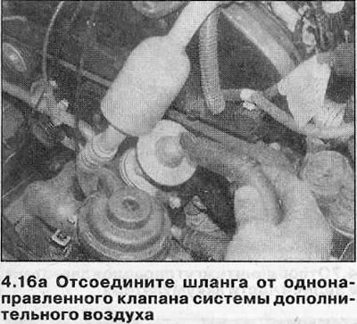
- e) Disconnect the air hose from the auxiliary air system one-way valve at the front of the engine (see illustration).
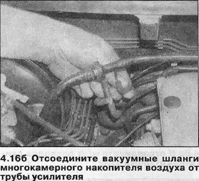
- and) Disconnect the carbon filter hose from the cleaning valve and the vacuum hoses of the multi-chamber air accumulator from the booster vacuum tube (see illustration).
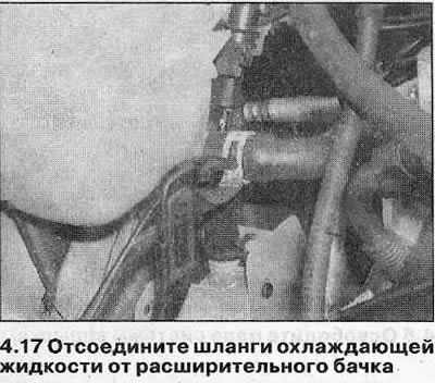
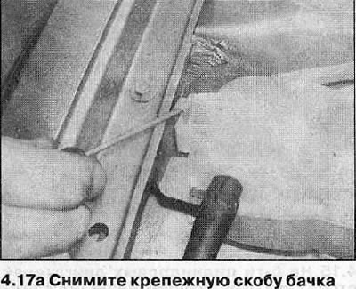
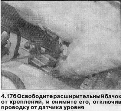
17. Release the mounting brackets and disconnect the coolant hoses from the expansion tank. Remove the mounting bracket and remove the tank from the engine compartment, disconnecting the wiring from the level sensor (see illustrations).
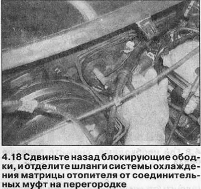
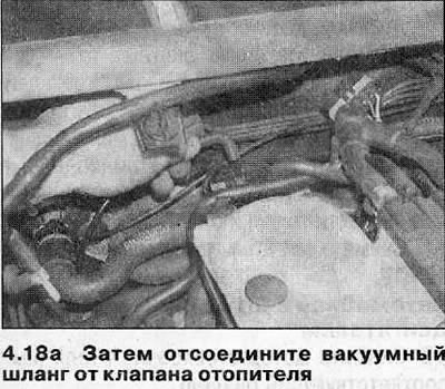
18. Locate the heater matrix cooling system hose couplings on the bulkhead. Separate both hoses from the couplings. Disconnect the vacuum hose from the heater valve (see illustrations).
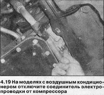
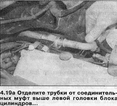
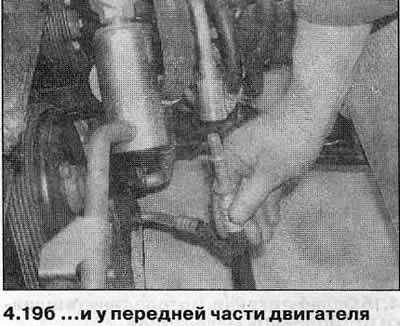
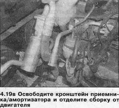
19. On air-conditioned models, disconnect the wiring connector from the compressor. Contact a specialist and discharge the air conditioning system. Then disconnect the refrigerant pipes (see related section) from the couplers on the receiver and above the left cylinder head. Plug the ends of the pipes immediately to prevent moisture from the air from entering the system. Loosen the mounting clamp bolts and slide the shock absorber away from the engine (see illustrations).
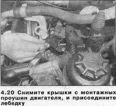
20. Attach the winch to the engine mounting lugs, then remove the transmission assembly as described in Section 7A or 7B (see illustration).
21. Once again check up that nothing interfered with removal of the engine. Secure all wiring/hoses so that they are not damaged when removed.
22. Unscrew the mounting bolts, and remove the vibration dampers (where there are) from the left and right engine mounts.
23. Remove the nuts securing the left and right engine mounts to the subframe and support brackets.
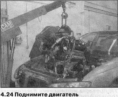
24. Raise the engine until the brackets are free from the mounts, then remove both mounts from the vehicle. Carefully move the engine forward and lift it out of the engine compartment (see illustration). Be especially careful that no components are pinched or damaged during removal.
25. Lower the engine to a clean surface, and disconnect the winch.
Installation
26. Connect the winch to the engine mounting lugs and carefully lift the unit into the engine compartment.
27. Align the engine brackets with the left and right hangers, and lower the engine onto the rubber pads. Check that the brackets are properly connected to the fasteners, then install the mounting nuts and tighten them with the tightening torque specified specifications.
28. Further installation is carried out in the reverse order of removal, pay attention to the following:
- A) Install the transmission unit as described in Section 7A or 7B.
- b) On 6-cylinder air-conditioned models, install new O-rings on the compressor couplers and connect the pipes securely. Finally, contact a specialist and charge the air conditioning system with refrigerant.
- V) Make sure all wiring is properly routed and secured with all brackets, and that all connectors are properly and securely connected.
- G) Make sure all disturbed hoses are properly connected and securely clipped.
- d) Adjust the throttle cable (see related section).
- e) Install a new oil filter (where necessary) and fill the engine with oil (see related section).
- and) Fill the cooling system (see related section).

Visitor comments