Examination
The nozzles inject fuel intermittently in the form of a cone-shaped jet and close tightly after injection. Leaky injectors make it difficult to start a hot engine. Defective injectors can sometimes cause extra fuel and lead to engine misfire.
1. Start the engine and let it idle.
2. With the engine running, listen with a stethoscope to each injector individually for clicks. These sounds appear when opening and closing the nozzle. If a stethoscope is not available, then the operation of the nozzles can be determined by touch with a screwdriver or fingers.
If the noises characteristic of valve injectors are not audible, or vice versa, unusual noises occur, then it is necessary to check the voltage supply to the injector, the signal from the control unit and its resistance to the injector by contacting the workshop.
Removing
Cars with 16-valve engine
3. Disconnect the wire terminal from the battery «masses» (-).
4. Disconnect the plugs of the coolant temperature sensor 1, the mass air flow sensor 2, and the throttle opening angle potentiometer (see illustration).
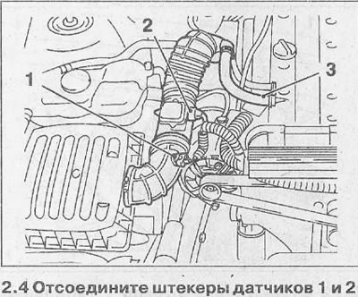
5. Disconnect the crankcase ventilation hose 3 from the cylinder head cover (see illustration 2.4).
6. Disconnect the air supply hose from the air filter and throttle by loosening the clamps.
7. Disconnect hose 1 from the cylinder head cover, and low pressure hose 3 from the fuel pressure regulator, as well as the wire «masses» (-) 2 - from the distribution pipeline (see illustration).
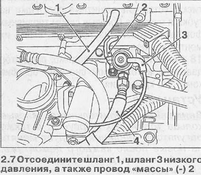
8. Disconnect the return fuel line 4 from the distribution fuel line, holding the connecting pipe from turning with a wrench (see illustration 2.7).
9. Disconnect the fuel supply line 1, the connecting pipe from turning with a wrench (see illustration)
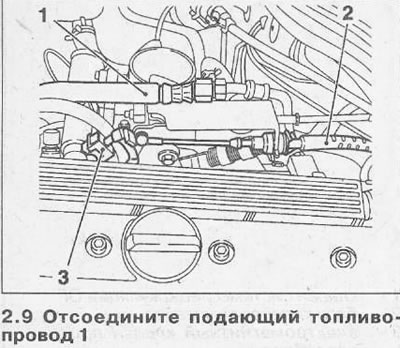
10. Disconnect the cable 2 of the accelerator and the plug 3 of the idle speed controller (see illustration 2.9).
11. Disconnect six plugs from the connector strip (see illustration).
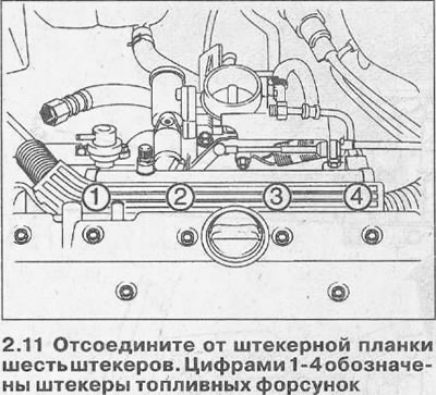
12. Squeeze out the brackets for fastening the fuel injectors of cylinders 1-4 with a screwdriver and catch the brackets with a magnet. Otherwise, they will fall.
13. Remove the plug strip by pushing it up.
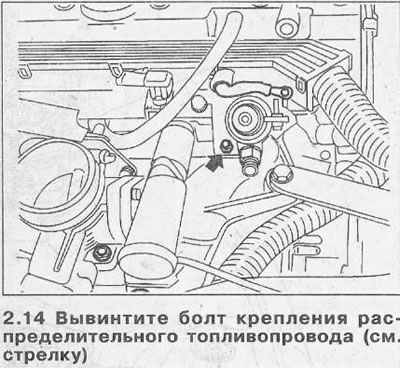
14. Unscrew a bolt of fastening of a distributive fuel line (see arrow in illustration).
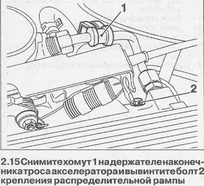
15. Remove clamp 1 on the holder of the accelerator cable tip and unscrew the bolt 2 of the distribution ramp fastening (see illustration).
16. Remove the distribution rail along with the injectors from the intake manifold (see illustration).
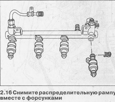
17. Clamp the distribution rail in a vise, installing protective gaskets on the jaws and remove the side brackets of the fuel injectors, having previously marked their mounting position.
18. Remove, if necessary, the pressure regulator in the fuel system by loosening its clamp.
Installation
Attention! The sealing rubber rings of the fuel injectors, as well as the pressure regulator, should be replaced with new ones after each dismantling, lubricating them with a thin layer of petroleum jelly before installation.
19. Install the fuel injectors on the distribution rail and secure them with brackets 1 (see illustration).
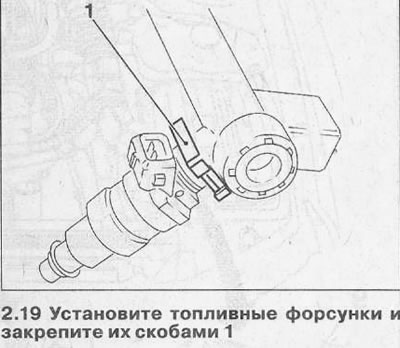
Attention! The brackets on the injectors should be installed as shown in illustration 2.19. Otherwise, they will interfere with the installation of the plug strip.
20. Install the distribution ramp on the cylinder head and secure with two bolts with a force of 8 Nm.
Further installation of dismantled parts is carried out in the reverse order of removal.
21. Start the engine and stop it, and then check the fuel system for leaks.
Vehicles with V6 engine
Removing
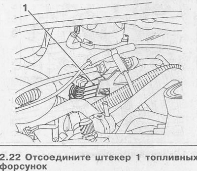
22. Remove the inlet jumper and disconnect the plug 1 of the fuel injectors, releasing it from the mount (see illustration).
23. Remove two bolts 1 (see illustration). When installing, they must be tightened to 15 Nm.
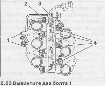
24. Unscrew the union nut 2, which secures the fuel supply line, and the nut 3 of the return fuel line (see illustration 2.23). When unscrewing the nuts, keep the distribution rail from turning.
25. Remove the wire harness guide, if any, and unscrew the bolts 4 that secure the distribution ramp (see illustration 2.23).
26. Remove the distribution rail along with the fuel injectors.
Installation is carried out in the reverse order of removal. The tightening torque for the distribution rail bolts is 8 Nm. When installing the ramp, make sure that the nozzles are correctly attached to it.
The tightening torque of the union nuts of the fuel return and supply lines to the distribution rail is 15 Nm.

Visitor comments