Tightening torques for threaded connections, Nm
- Connecting branch pipe of the distribution fuel line to the intake manifold - 8
- Connecting branch pipe of a distributive fuel pipeline - 15
- Starter to cylinder block - 45
- Fuel distribution line to flange - 20
- Flange of a distributive fuel line to a head of the block of cylinders — 20
- Drive disc/flywheel to crankshaft — 65 + 30°and 15°turns (bolts must be replaced with new ones after each dismantling and installed with red sealant)
- Exhaust manifold to cylinder head - 20 (nuts must be replaced after each disassembly)
- Oil filter cap - 25
- Cover of a radiator of a heater to the case of a heater — 30
- Cover of a heater to the block of cylinders — 20
- Ignition block to cylinder head - 8
- Vibration damper to the gear on the crankshaft - 20
- Throttle valve to intake manifold - 8
- The pressure head pipeline to the pump of the hydraulic booster of a steering — 28
- Accelerator pedal to bulkhead - 20
- Support leg to the anti-roll bar - 65 (nuts must be replaced after each disassembly)
- Generator to cylinder block and oil pump - 35
- Transmission to the block of cylinders. Bolts M8 - 20
- Transmission to the block of cylinders. Bolts M12 - 60
- Gearbox support to the body - 45 (bolts are installed with red sealant)
- Tension rollers for toothed and ribbed belts - 40
- An arm of fastening of auxiliary units to the block of cylinders — 35
- Crankshaft speed sensor to cylinder block - 8
- Crankshaft speed sensor gear - 15 (bolt must be replaced after each disassembly)
- Air conditioner pipelines to the compressor - 40
- Water pump drive pulley - 8 + 30°and 30°turns (the bolt must be replaced with a new one after each dismantling)
- Power steering pump pulley - 8 + 30°and 30°turn (the bolt must be replaced with a new one after each dismantling)
- Auxiliary drive belt tensioner to cylinder head - 35
- Knock sensor to cylinder block - 20
- Fuel lines to the connecting pipe - 15
- Cooling block to cylinder head - 30 (replace copper rings with new ones)
- The pipeline of cooling to the block of cylinders — 20
- Water pump to cylinder block - 25
- The pipeline of cooling to a head of the block of cylinders - 25
- Ball joint to the steering knuckle - 100 (replace nuts with new ones)
- Main bearing housing to cylinder block - 20
- Main bearing caps and main bearing housing to cylinder block - 50 + 60°and 15°turn (bolts must be replaced with new ones after each dismantling)
- Lambda probe in the exhaust pipe - 30 (black grease)
- Lever to steering shaft — 160 (replace old nuts with new ones)
- Front engine mount to bracket - 40
- Front engine support to the body - 55
- Engine mount to cylinder block - 60
- Camshaft bearing caps to cylinder head - 8
- Camshaft gear - 50 + 60°and 15°turns (bolt must be replaced after each disassembly)
- Camshaft position sensor - 8
- Oil pan drain plug with socket head - 10
- Oil pan drain plug with hex head - 55
- Engine oil pressure sensor to oil pump - 40
- Oil filter to the cylinder block - 45
- Oil pipelines to the cooling radiator - 30 + turn by 30°and 15° (bolt must be replaced after each disassembly)
- Oil lines to the cylinder block - 30
- Oil pump to cylinder block. Bolts M8 - 12 + 20 (with red sealant. An additional turn of 20 Nm is performed after installing the lower generator mounting bolt)
- Supply and return oil lines to the cylinder block - 30
- Oil pan for transmission. Bolts M8 - 20
- Oil pan for transmission. Bolts M10 - 40
- The upper part of the oil pan to the cylinder block and oil pump - 15
- The lower part of the oil pan to the top - 8 + turn 30° (bolts must be replaced with new ones)
- Connecting rod cap - 35 + 45°and 15°turn (bolts must be replaced with new ones)
- Wheel bolts - 110
- Gearshift lever to the box - 20
- The tip of the transverse tie rod to the steering knuckle - 60 (nut must be replaced)
- Coolant temperature sensor - 18
- Intake manifold bracket to cylinder block - 25
- Thermostat housing - 20
- Brake booster hose to intake manifold - 20
- Air conditioning compressor to bracket - 35
- Pressure reducing valve to the oil pump - 60
- Safety valve to the oil pump - 30
- Front cross member to the body — 65 + 30°and 15°turns (bolts must be replaced after each disassembly)
- Front bolts for fastening the front cross member - 150 + 30°and 15°turns (bolts must be replaced after each disassembly)
- Rear front end cross member mounting bolts - 130 + 30°and 15°turns (bolts must be replaced after each disassembly)
- Downpipe to exhaust manifold - 30
- Toothed belt guide roller to cylinder block, bracket and oil pump - 40
- Toothed belt gear to crankshaft - 250 + 45°and 15°turns (bolts must be replaced after each disassembly)
- Spark plugs - 25
- Cylinder head - 25 + 90°+ 90°+ 90°and 15°turns (bolts must be replaced after each disassembly. Subsequent pull-ups are not allowed)
Cylinder head and valves (see illustration 0.0)
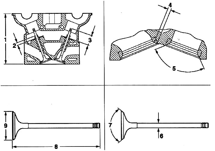
0.0 Cylinder head and valves
1 - cylinder head height
2 - protrusion of the valve guide
3 - protrusion of the valve stem
4 - the width of the valve seat in the cylinder head
5 - the angle of the seat chamfer of the valve seat in the cylinder head
6 - valve stem diameter
7 - chamfer angle of the valve seat
8 - valve stem length
9 - valve disc diameter
X25XE, X30XE, Y26SE, Y32SE engines
Cylinder head height, mm - 134
Width of a landing saddle of the valve in a head of the block of cylinders, mm
- intake valves - 1.0-1.4
- exhaust valves - 1.0-1.8
The angle of the landing chamfer of the valve seat in the cylinder head is 90°
Valve guide diameter, mm
- nominal size - 6,000-6,012
- 1st repair size - 6.075-6.090
Valve guide length, mm
- intake valves - 44.70-45.30
- exhaust valves - 34.70-35.30
Valve guide protrusion, mm
- intake valves - 13.7-14.0
- exhaust valves - 13.7-14.0
Valve stem protrusion, mm
- nominal size - 39.6-40.2
- 1st repair size (0,075) — 39,2-39,8
Valve stem length, mm
- intake valves - 101.9-102.3
- exhaust valves - 92.05-92.45
1st repair size (0,075)
- intake valves - 101.5-101.9
- exhaust valves - 91.65-92.05
Valve stem diameter, mm
- intake valves - 5.955-5.970
- exhaust valves - 5.945-5.960
1st repair size
- intake valves - 6.030-6.045
- exhaust valves - 6.020-6.035
Valve stem clearance, mm
- intake valves - 0.030-0.057
- exhaust valves - 0.040-0.067
Permissible ovality of the valve stem, mm - 0.03
Valve disc diameter, mm
- intake valves - 31.9-32.1
- exhaust valves - 28.9-29.1
The angle of the landing chamfer of the valve seat in the cylinder head - 90°40'
Attention! Grinding of the cylinder head is not permitted.
Crankshaft (see illustration 0.0a)
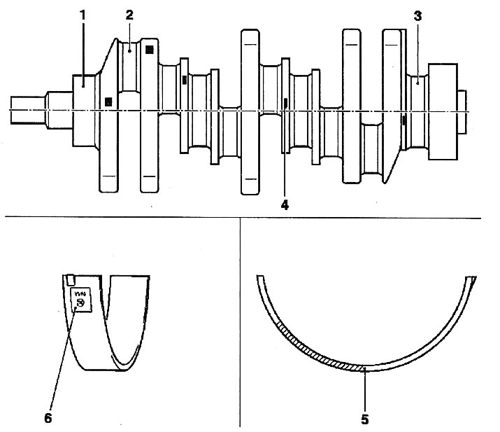
0.0a Crankshaft
1 - journals of main bearings
2 - necks of connecting rod bearings
3 - the neck of the middle main bearing
4 - color marking
5 - color marking of liners
6 - designation of liners
X25XE, X30XE, Y26SE, Y32SE engines
Diameter of necks of a cranked shaft, mm
main journals 1-3 - color marking
- 67.980-67.988 - green
- 67.988-67.996 - brown
1st repair size (0,25)
- 67.730-67.738 - green/blue
- 67.738-67.746 - brown/blue
2nd repair size (0,50)
- 67.480-67.488 - green/white
- 67.488-67.496 - brown/white
medium neck 4
nominal size
- 24,500-24,552
1st repair size (0,25)
- 24,700 - 24,752
2nd repair size (0,50)
- 24,900-26,952
X25XE, Y26SE engines
connecting rod journals 1-6 - color marking
nominal size
- 48,971-48,990
1st repair size (0,25)
- 48.721-48.740 - blue
2nd repair size (0,50)
- 48.471-48.490 - white
X30XE, Y32SE engines
connecting rod journals 1-6 - color marking
nominal size
- 53,971-53,990
1st repair size (0,25)
- 53.721-53.740 - blue
2nd repair size (0,50)
- 53.471-53.490 - white
X25XE, X30XE, Y26SE, Y32SE engines
Lower shells of main bearings
color marking - thickness, mm
nominal size
- brown - 1.989-1.995
- green - 1.995-2.001
1st repair size (0,25)
- brown / blue - 2.114-2.120
- green / blue - 2.120-2.126
2nd repair size (0,50)
- brown/white - 2.239-2.245
- green/white - 2.245-2.251
Upper main bearing shells
color marking - thickness, mm
nominal size
- brown - 1.989-1.995
- green - 1.995-2.001
1st repair size (0,25)
- brown / blue - 2.114-2.120
- green / blue - 2.120-2.126
2nd repair size (0,50)
- brown/white - 2.239-2.245
- green/white - 2.245-2.251
Nominal clearance of main bearings, mm - 0.014 - 0.043
X25XE, X30XE, Y26SE, Y32SE engines
Lower conrod bearing shells
color marking - thickness, mm
nominal size
- 1,490- 1,500
1st repair size (0,25)
- blue - 1.615-1.625
2nd repair size (0,50)
- white - 1.740-1.750
Upper connecting rod bearings
color marking - thickness, mm
nominal size
- 1,490-1,500
1st repair size (0,25)
- blue - 1.615-1.625
2nd repair size (0,50)
- white - 1.740-1.750
Rated clearance of connecting rod bearings, mm - 0.0010-0.061
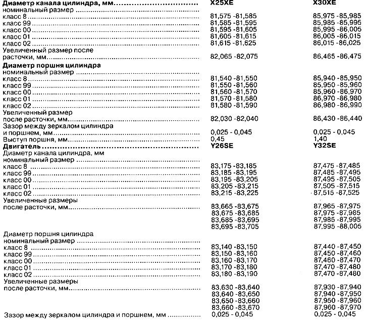
Cylinder block (see illustration 0.0b)
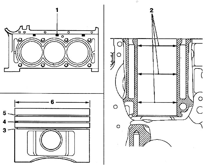
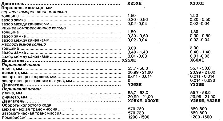
0.0b Cylinder block
1 - cylinder class
2 - cylinder bore diameter
3 - oil scraper ring with expansion spring
4 - lower compression ring
5 - top trapezoidal compression ring
6 - piston diameter

Visitor comments