
Removal
1. Remove the cover under the steering wheel to connect the diagnostic tool (Fig. 9.53).
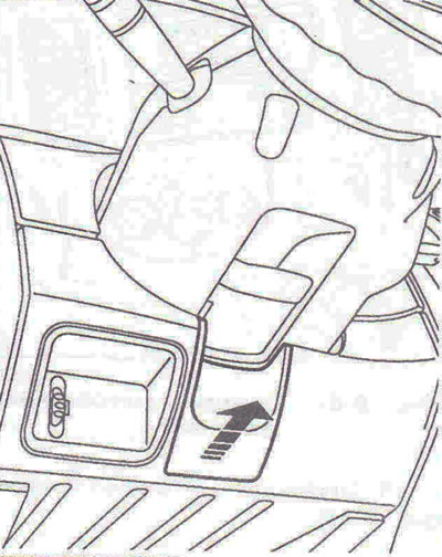
Fig. 9.53. Remove the cover under the steering wheel to connect the diagnostic tool.
2. Disconnect the battery.
3. Disconnect the airbag from the steering wheel (Fig. 9.54). Disconnect the wiring connector from the airbag.
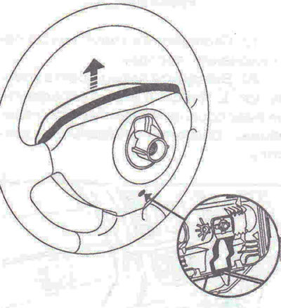
Fig. 9.54. Disconnect the airbag from the steering wheel.
4. Unscrew the steering wheel mounting bolt and remove the steering wheel.
5. Remove the front pillar trims (Fig. 9.55).
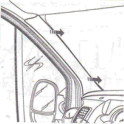
Fig. 9.55. Remove the front pillar trims.
6. Disconnect the antenna wiring connector (Fig. 9.56).
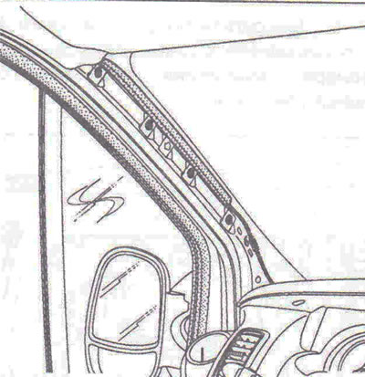
Fig. 9.56. Disconnect the antenna wiring connector.
7. Remove the instrument panel visor (Fig. 9.57).
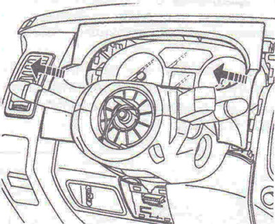
Fig. 9.57. Remove the instrument panel visor.
8. Unscrew the two bolts A securing the steering column covers (Fig. 9.58). Unlock the steering wheel height adjuster. Disconnect the lower steering column cover 1, then 2.
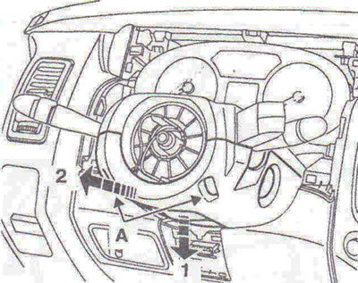
Fig. 9.58. Unscrew the two bolts A securing the steering column covers. Unlock the steering wheel height adjuster. Disconnect the lower steering column cover 1, then 2.
9. Disconnect the wiring connectors, unscrew bolt B, then release the contact ring assembly (Fig. 9.59).
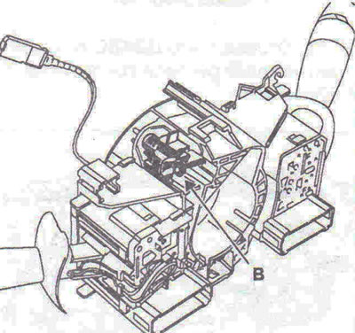
Fig. 9.59. Disconnect the wiring connectors, unscrew bolt B, then release the contact ring assembly.
10. Remove the transponder ring C, unscrew the two bolts D securing the instrument panel, remove the instrument panel, plate E, and then disconnect the wiring connectors (Fig. 9.60).
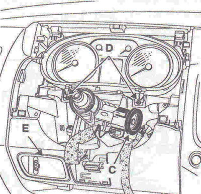
Fig. 9.60. Remove the transponder ring C, unscrew the two bolts D securing the instrument panel, remove the instrument panel, plate E, and then disconnect the wiring connectors.
11. Disconnect the diagnostic connector F and the ignition switch wiring connector G (Fig. 9.61).
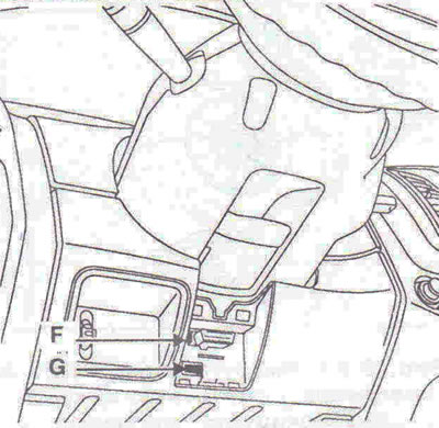
Fig. 9.61. Disconnect the diagnostic connector F and the ignition switch wiring connector G.
12. Disconnect the UCH N (it is located near the steering column) (Fig. 9.62).
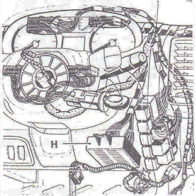
Fig. 9.62. Disconnect the UCH H (it is located near the steering column).
13. Unscrew the mounting bolts I and lock the steering wheel height adjuster (Fig. 9.63).
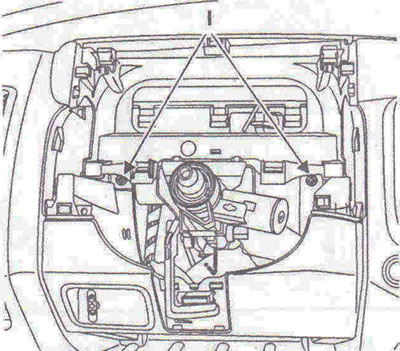
Fig. 9.63. Unscrew the mounting bolts I and lock the steering wheel height adjuster.
14. Remove the six bolts securing the passenger airbag (Fig. 9.64). Disconnect the wiring connector, then release the airbag.
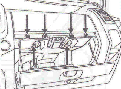
Fig. 9.64. Remove the six bolts securing the passenger airbag.
15. Remove the J mounting bolts and disconnect the wiring connector from the glove box light (Fig. 9.65).
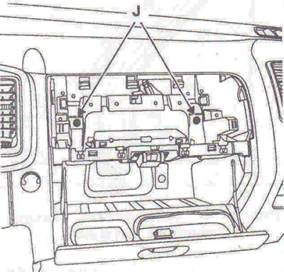
Fig. 9.65. Remove the mounting bolts J and disconnect the wiring connector from the glove box light.
16. Remove the upper center cover. Remove the car radio (using the MS. 1373 device) (Fig. 9.66).
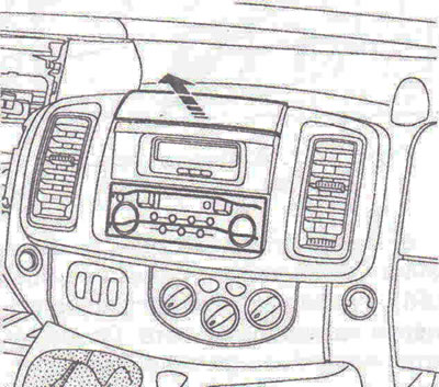
Fig. 9.66. Detach the upper center cover. Remove the car radio (using the device MS. 1373).
17. Remove the central display (Fig. 9.67).
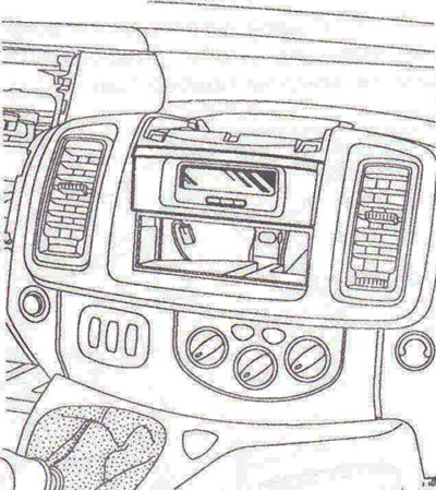
Fig. 9.67. Remove the central display.
18. Unscrew the mounting bolts K (Fig. 9.68).
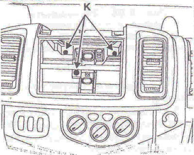
Fig. 9.68. Unscrew the mounting bolts K.
19. Disconnect the gear shift lever cover.
20. Unscrew the four L mounting bolts (Fig. 9.69). Disconnect the hazard warning light wiring connector. Remove the center console.
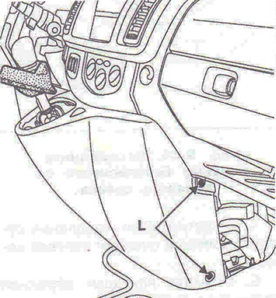
Fig. 9.69. Unscrew the four L mounting bolts.
21. Unscrew the mounting bolt M (Fig. 9.70). Disconnect the wiring connectors, then remove the heater control panel.
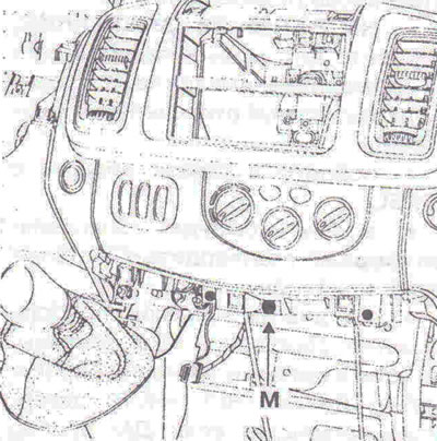
Fig. 9.70. Unscrew the mounting bolt M.
22. Loosen the mounting bolts N and disconnect the connecting wire on «mass» ABOUT (Fig. 9.71).
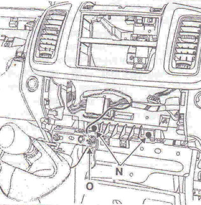
Fig. 9.71. Unscrew the mounting bolts N and disconnect the connecting wire on «mass» ABOUT.
23. Disconnect the wiring connectors (Fig. 9.72).
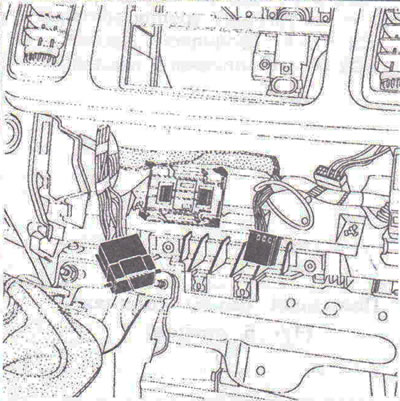
Fig. 9.72. Disconnect the wiring connectors.
24. Detach the ashtray holders (Fig. 9.73).
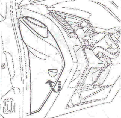
Fig. 9.73. Detach the ashtray holders.
25. Remove the four side fasteners P (Fig. 9.74).
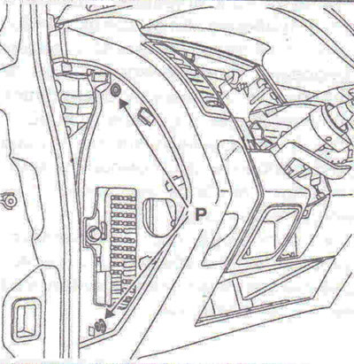
Fig. 9.74. Remove the four side fasteners P.
Attention! The following operations are carried out by two auto mechanics.
26. Partially release the instrument panel. Disconnect the wiring connectors from the speakers. Remove the instrument panel.
Installation
27. Installation is carried out in the reverse order of removal.
Features of installation of a slip ring
28. Make sure the wheels are set to the straight-ahead position. Tighten the contact ring mounting bolt. Connect the wiring connectors.
Features of steering wheel installation
29. There are special guides in the splines of the steering wheel hub (Fig. 9.75). The steering wheel should fit freely onto the splines of the steering column. Try not to damage them.
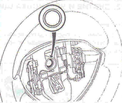
Fig. 9.75. The steering wheel hub splines have special guides.
30. After each removal, be sure to replace the steering wheel mounting bolt; when installing, tighten it to a torque of 44 Nm.
Features of installing the driver's airbag
31. Connect the wiring connector, then lock its retainer (Fig. 9.76). Place the cushion on the steering wheel and slide it down until it clicks into place.
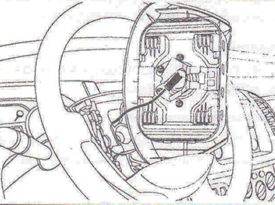
Fig. 9.76. Connect the wiring connector, then lock its retainer.
Features of installing a passenger airbag
32. Be sure to observe the tightening torque of the mounting bolts: four bolts 0-2 Nm, two bolts P -8 Nm (Fig. 9.77).
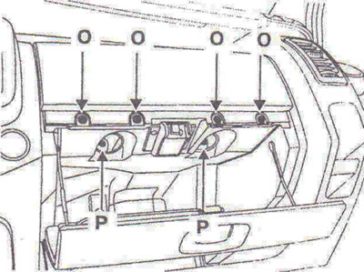
Fig. 9.77. Be sure to observe the tightening torque of the mounting bolts: four bolts 0-2 Nm, two bolts P - 8 Nm.
33. Perform a check using a diagnostic tool.
Visitor comments