
Removal
1. Disconnect the battery.
2. Unscrew bolt 1 of the expansion tank and move it to the side (Fig. 4.102).
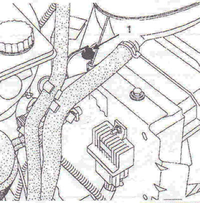
Fig. 4.102. Unscrew bolt 1 securing the expansion tank and move it to the side.
3. Remove the boost pressure control solenoid valve 2, disconnect the wiring connector 3 from the pre-heating and post-heating unit (Fig. 4.103). Unscrew the 4 bolts securing the protective cover and remove it.
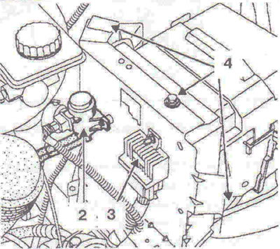
Fig. 4.103. Remove the boost pressure control solenoid valve 2, disconnect the wiring connector 3 from the pre-heating and post-heating unit. Unscrew the bolts 4 securing the protective cover and remove it
4. Unscrew the bolts 5 securing the control unit and remove it, having first disconnected the wiring connectors from the unit (Fig. 4.104).
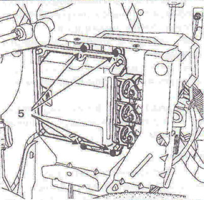
Fig. 4.104. Unscrew the bolts 5 securing the control unit and remove it, having first disconnected the wiring connectors from the unit.
Installation
5. Installation is carried out in the reverse order of removal.
Visitor comments