
Removal
1. To prevent the crankshaft from turning, screw in the two bolts 1 securing the flywheel to the crankshaft, then insert the lever 2 between the two bolts (Fig. 2.61).
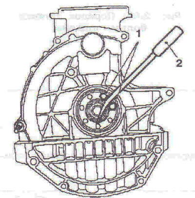
Fig. 2.61. To prevent the crankshaft from turning, screw in two bolts 1 securing the flywheel to the crankshaft, then insert lever 2 between the two bolts.
2. Unscrew the central bolt 2 and remove the crankshaft pulley 1 (Fig. 2.62).

Fig. 2.62. Unscrew the central bolt 2 and remove the crankshaft pulley 1.
3. Remove the cylinder head.
4. Turn the engine 180°using the KM-412 stand.
5. Unscrew the twenty-two bolts securing the pan 1 and remove it (Fig. 2.63). Remove gasket 2.
6. Remove the cylinder block oil deflector by unscrewing bolt 1 and unhooking the two fasteners (Fig. 2.64).

Fig. 2.63. Unscrew the twenty-two bolts securing the pan 1 and remove it. Remove the gasket 2.

Fig. 2.64. Remove the cylinder block oil deflector by unscrewing bolt 1 and unhooking the two fasteners.
7. Remove the oil pump together with the pulley by unscrewing the two bolts 2, the crankshaft pulley 1 and the oil pump drive chain (Fig. 2.65).

Fig. 2.65. 7. Remove the oil pump together with the pulley by unscrewing two bolts 2, crankshaft pulley 1 and the oil pump drive chain.
8. Apply identification marks 1 to the four connecting rod caps (Fig. 2.66). Remove the connecting rod cover of the 1st cylinder by unscrewing two bolts (the first cylinder is located on the flywheel side). Remove the piston of the first cylinder.

Fig. 2.66. Apply identification marks 1 to the four connecting rod caps.
9. Move the piston down using handle 2 of the hammer (Fig. 2.67).

Fig. 2.67. Move the piston down using handle 2 of the hammer.
Installation
10. Lubricate the piston and piston installation mandrel with engine oil 1 (Fig. 2.68). Install new connecting rod bearings. Install the piston of the first cylinder.

Fig. 2.68. Lubricate the piston and piston installation mandrel 1 with engine oil.
11. When installing the pistons, observe the direction of the mark on the pistons, which should be directed towards the flywheel.
12. Further installation is carried out in the reverse order of removal. The order of tightening the pan bolts is shown in Fig. 2.69.

Fig. 2.69. Sequence of tightening the pan bolts.
Visitor comments