Permissible deformation
Cylinder head - 0.05 mm.
Cylinder block - 0.03 mm.
Pistons
The piston dimensions are shown in Fig. 2.42.
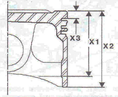
Fig. 2.42. Piston dimensions.
- X1 - 43.8±0.01 mm.
- X2 - 56.8 mm.
- ХЗ - 6±0.1 mm.
Piston diameter (category 2 or B) - 82.680-82.690 mm.
Piston diameter (category 3 or C) - 82.690-82.700 mm.
The piston marks are shown in Fig. 2.43.
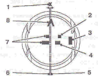
Fig. 2.43. Piston marks: 1 - Distance between the center of the hole for the piston pin 6 and the axis of symmetry 5 of the piston; 3 - Engine suffix (2.0 for F4R); 4, 7 - Used by the manufacturer; 5 - Piston symmetry axis; 6 - Center of the piston pin hole; 8 - Direction of piston installation.
Piston pin
Inner diameter - max. 12.6 mm.
Outside diameter - 20.99521.000 mm.
Length - 60.7-61.00 mm.
Connecting rods
The distance between the centers of the upper and lower connecting rod heads is 144±0.035 mm.
The diameter of the connecting rod upper head bushing is 23.010±0.010 mm.
Connecting rod bearing thickness -1.776±0.003 mm.
Inner diameter of the lower connecting rod head (without insert) -51.596±0.009 mm.
Inner diameter of the lower connecting rod head (with inserts) -48.044±0.009 mm.
Axial runout - 0.22-0.40 mm.
Radial clearance - 0.020-0.070 mm.
Attention! The maximum permissible difference in weight between the connecting rods must not exceed 6 tram.
Crankshaft
Number of main bearings - 5.
Longitudinal runout of the crankshaft - 0.07-0.23 mm.
Crankshaft lateral runout: 0.040-0.075 mm.
Main bearing inner diameter: blue - 54.78554.794 mm, red - 54.79554.805 mm.
Main bearing thickness: blue - 1.944-1.950 mm, red - 1.939-1.945 mm.
Cylinder head
Cylinder head height H - 138.15 mm (Fig. 2.44).
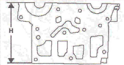
Fig. 2.44. Cylinder head height H.
Camshafts
The camshafts are identified by horizontal and vertical marks (Fig. 2.45).
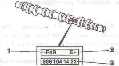
Fig. 2.45. Identification of the camshaft: 1 - Engine type; 2 - Intake A or outlet E; 3 - Used by the manufacturer.
Number of main bearings - 6.
The diameter of the camshaft main journal: 1st - 25±0.03 mm, 2-5 - 25±0.021 mm, 6th - 28±0.061 mm.
Inner diameter of the bore for main bearings: 1-5 - 25±0.061 mm, 6 - 28±0.061 mm.
Valves and guide bushings
The clearance adjustment is automatic using hydraulic compensators.
Valve guide length: 40.5±0.15 mm.
The outer diameter of the valve guide bushing is 11 + 0.068 mm.
Inner diameter of valve guide bushing: unmachined -5 + 0.075 mm, machined - 5.5 +0.018 mm.
Valve guide installation angle: inlet valve - 63' ZOG. outlet valve - 66".
Installing the valve guide bushing (Fig. 2.46): inlet valve A - 12±0.15 mm, outlet valve B -11±0.15 mm.
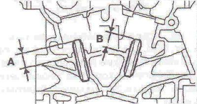
Fig. 2.46. Installing valve guide bushings.
Rod diameter A (Fig. 2.47): inlet valve - 5.471±0.009 mm, outlet valve - 5.447±0.009 mm.
Plate diameter B: inlet valve - 33.5±0.12 mm, outlet valve - 29.0±0.12 mm.
Length C: inlet valve -110.08±0.15 mm, outlet valve - 108.87±0.15 mm.
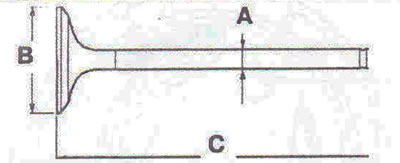
Fig. 2.47. Valve dimensions. A - Rod diameter; B - Plate diameter; C - Length;
Valve seats
Valve seat angle - 89".
The outer diameter of the intake valve seat is 34.542±0.008 mm.
The outer diameter of the exhaust valve seat is 30.042±0.006 mm.
Inner diameter of the inlet valve seat insert is 34.4 + 0.02 mm.
The inner diameter of the exhaust valve seat insert is 29.9 + 0.02 mm.
Valve seat height - 4.65±0.05 mm.
Inlet valve seat width -1.3+ 1.4 mm.
Exhaust valve seat width - 1.4 + 1.3 mm.

Visitor comments