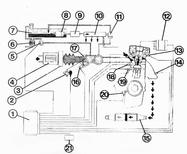
Simtec four-point injection system in 1.8 / 2.0 l engines:
1 - control unit;
2 - throttle potentiometer;
3 - air mass flow meter;
4 - air filter;
5 - ventilation valve;
6 - container with activated carbon;
7 - fuel tank;
8 - fuel pump;
9 - fuel filter;
10 - distribution pipeline;
11 - pressure regulator;
12 - DIS ignition module;
13 - camshaft position sensor;
14 - lambda probe;
15 - catalytic converter;
16 - idle speed regulator;
17 - intake manifold;
18 - coolant temperature sensor;
19 - knock sensor;
20 - crankshaft sensor;
21 - diagnostic connector.
Control block
between input information (from different sensors) and intake valves is the control unit.
Depending on the various load and temperature conditions, the control unit allocates a very specific amount of fuel to the engine. To do this, the control unit changes the duration of the opening of the solenoid operated intake valves. Because the pressure in the fuel system is always constant, the amount of injected fuel can only change due to the duration of the injection.
Where does the control unit get the information on the basis of which it determines the injection time? Various sensors are involved in this:
- Intake air temperature sensor on the side of the air intake hose; gives information about the temperature of the intake air required for combustion.
- Intake manifold pressure sensor (only in Multitec-S) on the front wall; it is connected to the intake manifold and gives information about the existing reduced pressure.
- Hot-film air mass meter (only at Simtec); it determines the incoming intake air by weight.
- Coolant temperature sensor; it provides a comparative value for the engine temperature.
- throttle potentiometer; it informs about the current throttle position.
- Frequency sensor of the distance traveled; it informs about the speed of movement.
- Inductive pulse sensor; it is primarily important for ignition, and also gives a signal about the speed for injection (see ignition chapter).
- Camshaft position sensor; it gives a signal to ignite cylinder 1. This allows the control unit to determine which cylinder is next to receive a portion of gasoline based on the ignition sequence.
Nozzles
A nozzle is located in the suction channel of each cylinder of the engine. It passes into each cylinder the amount of fuel that is needed at the moment, and at the same time provides a fine spray of gasoline. The nozzles are controlled by an electromagnet. In this case, the nozzle needle rises in its seat by about 0.1 mm - fuel can flow.
The speed of reaction is interesting: the time of lifting and lowering is in the range of 2.2-2.9 ms.
Fuel distribution pipe
It serves to evenly supply fuel to all injectors. In addition, the distribution pipe acts as a fuel manifold and therefore does not allow pressure fluctuations.
Pressure regulator
It is located on the distribution pipeline. The pressure regulator ensures constant pressure in the fuel system. As the pressure rises, the regulator drains the fuel back into the fuel tank; as the pressure decreases, it reduces the return flow of fuel. By connecting a vacuum line to the intake manifold, it simultaneously receives engine load signals and at full load increases the pressure by approximately 0.5 bar. This injects the additional amount of fuel required at full power.
Fuel pump and relay
For more information about the electric fuel pump and fuel pump relay, see chapter «From fuel tank to fuel pump».
Intake air temperature sensor
The intake air temperature sensor is located on the side of the air intake hose. In addition to the intake manifold pressure sensor, it serves as a control unit for calculating the engine load. At high intake air temperatures (equals low air density) the injection time should, for example, be shortened and the ignition timing shifted slightly more to the side «delays».

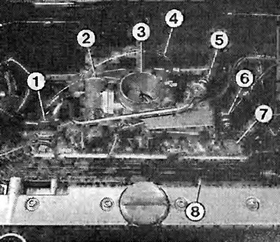
Simtec injection system components. The numbers indicate:
1 - fuel pressure regulator;
2 - idle speed regulator;
3 - throttle valve pipe;
4 - heating hose for the throttle valve pipe;
5 - return fuel line;
6 - injection fuel line;
7 - distribution pipeline;
8 - cable box.

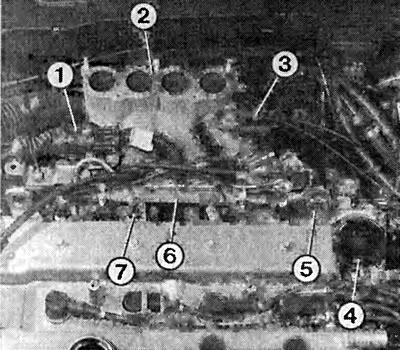
Here, the numbers indicate the nodes of the Multec-S injection system, namely:
1 - multi-pin connection;
2 - intake manifold:
3 - valve for ventilation of the fuel tank;
4 - throttle valve pipe;
5 - fuel pressure regulator;
6 - distribution pipeline;
7 - nozzle.
Intake manifold pressure sensor Multec-S
The pressure regulator is connected by a hose to the intake manifold. It is located on the back of the front wall next to the brake booster. The current pressure in the intake manifold affects the crystal chip in the pressure sensor. Depending on the pressure conditions, the resistance value of the crystal chip changes. Based on the change in resistance and the current speed, the control unit determines the load on the engine.
Simtec Hot Film Air Mass Meter
The air sucked in by the engine, after passing through the air filter, enters the air mass meter. This air mass meter can electronically produce a kind of «weighing» intake air. The electrically heated plate is located in the suction channel directly in the air stream. At idle, with the throttle closed, only a small amount of air flows past the heating plate, so it cools down slightly. By increasing the pressure on the gas pedal and a larger throttle opening angle, more air passes by the heating plate, cooling increases. By lowering the temperature, the electrical resistance of the plate changes and, consequently, the heating current changes. This change in current serves as an information signal for the control unit about the incoming air mass, i. about the weight of the air. Changes in air pressure and temperature can also be determined in the same way.
Throttle valve
Further behind in the intake air flow is a throttle valve. It is controlled by a cable from the gas pedal. It opens or closes the intake to the intake manifold and therefore to the combustion chambers of the engine.
Throttle Potentiometer
The throttle valve potentiometer is actuated by its shaft. The potentiometer determines the position of the throttle valve at the moment and reports this to the control unit. The control unit needs this load information to, among other things, adjust the idle speed, select the ignition characteristic and calculate the injection duration.
Idle speed controller
It is located behind the throttle valve. The idle speed controller is a small electric motor with a threaded spindle. It ensures that the idle speed is always constant - no matter if the engine is cold or warm, or powerful consumers of electricity are on (air conditioner). Ahead on the spindle is a conical chamfer of the valve. The idle air control regulates the passage of additional air through the bypass hole past the throttle valve. The governor has 256 setting options and is capable of adjusting the idle speed at all loads. It also performs tasks during the engine warm-up stage and to reduce or cut off traction.
Coolant temperature sensor
Coolant temperature is used to control many injection functions: cold start enrichment, post-launch enrichment (over the entire temperature range), enrichment of the combustible mixture during acceleration and shutdown of thrust. Information about the temperature of the coolant is also transmitted to the control unit in the form of a resistance value. It calculates the correct injection time, which can be between 2 and 8 ms when the engine is warm.
Impulse sensor, camshaft position sensor and knock sensor
Inductive encoder and camshaft position sensor are covered in chapter on ignition together with a description of operation and verification. The same applies to the knock sensor, which is only related to the ignition unit of the multipoint injection.

Visitor comments